
Steel Design (Activate Learning with these NEW titles from Engineering!)
6th Edition
ISBN: 9781337094740
Author: Segui, William T.
Publisher: Cengage Learning
expand_more
expand_more
format_list_bulleted
Related questions
Question
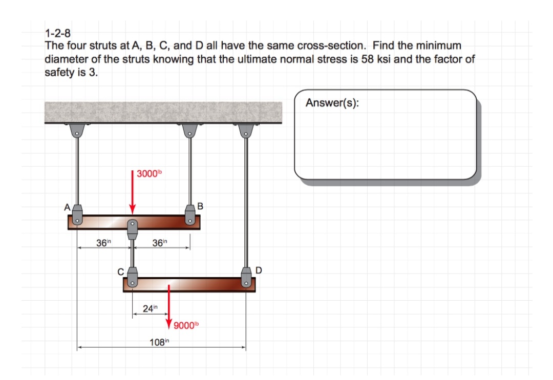

Transcribed Image Text:1-2-8
The four struts at A, B, C, and D all have the same cross-section. Find the minimum
diameter of the struts knowing that the ultimate normal stress is 58 ksi and the factor of
safety is 3.
36in
C
3000b
36in
24in
108in
B
9000⁰
D
Answer(s):
Expert Solution
This question has been solved!
Explore an expertly crafted, step-by-step solution for a thorough understanding of key concepts.

This is a popular solution

Trending nowThis is a popular solution!

Step by stepSolved in 3 steps with 3 images

Knowledge Booster


Learn more about
Need a deep-dive on the concept behind this application? Look no further. Learn more about this topic, civil-engineering and related others by exploring similar questions and additional content below.Similar questions
- A beam is part of the framing system for the floor of an office building. The floor is subjected to both dead loads and live loads. The maximum moment caused by the service dead load is 45 ft-kips, and the maximum moment for the service live load is 63 ft-kips (these moments occur at the same location on the beam and can therefore be combined). a. If load and resistance factor design is used, determine the maximum factored bending moment (required moment strength). What is the controlling AISC load combination? b. What is the required nominal moment strength for a resistance factor of 0.90? c. If allowable strength design is used, determine the required moment strength. What is the controlling AISC lead combination? d. What is the required nominal moment strength for a safety factor of 1.67?arrow_forwardRefer to Figure P6.4. A strip load of q = 900 lb/ft2 is applied over a width B = 36 ft. Determine the increase in vertical stress at point A located z = 15 ft below the surface. Given: x = 27 ft. Figure P6.4arrow_forwardThe data in Table 1.5.3 were obtained from a tensile test of a metal specimen with a rectangular cross section of 0.2011in.2 in area and a gage length (the length over which the elongation is measured) of 2.000 inches. The specimen was not loaded to failure. a. Generate a table of stress and strain values. b. Plot these values and draw a best-fit line to obtain a stress-strain curve. c. Determine the modulus of elasticity from the slope of the linear portion of the curve. d. Estimate the value of the proportional limit. e. Use the 0.2 offset method to determine the yield stress.arrow_forward
- Two line loads q1 and q2 of infinite lengths are acting on top of an elastic medium, as shown in Figure P8.6. Find the vertical stress increase at A.arrow_forwardCompare the engineering and true secant elastic moduli for the natural rubber in Example Problem 6.2 at an engineering strain of 6.0. Assume that the deformation is all elastic.arrow_forwardEB and FG are two planes inside a soil element ABCD as shown in Figure 10.50. Stress conditions on the two planes are Plane EB: EB = 25 kN/m2; EB = +10 kN/m2 Plane FG: FG = 10 kN/m2; FG = 5 kN/m2 (Note: Mohrs circle sign conventions for stresses are used above) Given ; = 25, determine: a. The maximum and minimum principal stresses b. The angle between the planes EB and FG c. The external stresses on planes AB and BC that would cause the above internal stresses on planes EB and FGarrow_forward
- A tensile test was performed on a metal specimen having a circular cross section with a diameter 0. 510 inch. For each increment of load applied, the strain was directly determined by means of a strain gage attached to the specimen. The results are, shown in Table: 1.5.1. a. Prepare a table of stress and strain. b. Plot these data to obtain a stress-strain curve. Do not connect the data points; draw a best-fit straight line through them. c. Determine the modulus of elasticity as the slope of the best-fit line.arrow_forwardA tensile test was performed on a metal specimen with a diameter of 1 2 inch and a gage length (the length over which the elongation is measured) of 4 inches. The dam were plotted on a load-displacement graph. P vs. L. A best-fit line was drawn through the points, and the slope of the straight-line portion was calculated to be P/L =1392 kips/in. What is the modulus of elasticity?arrow_forwardCompute the nominal shear strength of an M107.5 of A572 Grad 65 steel.arrow_forward
- For the beam shown: (a) determine the distance a for which the maximum positive and negative bending moments in the beam are equal; and (b) draw the corresponding shear and bending moment diagrams for the beam.arrow_forwardThe results of a tensile test are shown in Table 1.5.2. The test was performed on a metal specimen with a circular cross section. The diameter was 3 8 inch and the gage length (The length over which the elongation is measured) was 2 inches. a. Use the data in Table 1.5.2 to produce a table of stress and strain values. b. Plot the stress-strain data and draw a best-fit curve. c. Compute the, modulus of elasticity from the initial slope of the curve. d. Estimate the yield stress.arrow_forwardEstimate the elastic and plastic strain at the ultimate tensile strength in the low-carbon steel specimen in Figure 6.16.arrow_forward
arrow_back_ios
SEE MORE QUESTIONS
arrow_forward_ios
Recommended textbooks for you
- Steel Design (Activate Learning with these NEW ti...Civil EngineeringISBN:9781337094740Author:Segui, William T.Publisher:Cengage Learning
 Principles of Foundation Engineering (MindTap Cou...Civil EngineeringISBN:9781305081550Author:Braja M. DasPublisher:Cengage Learning
 Materials Science And Engineering PropertiesCivil EngineeringISBN:9781111988609Author:Charles GilmorePublisher:Cengage Learning
  Engineering Fundamentals: An Introduction to Engi...Civil EngineeringISBN:9781305084766Author:Saeed MoaveniPublisher:Cengage Learning
 Principles of Foundation Engineering (MindTap Cou...Civil EngineeringISBN:9781337705028Author:Braja M. Das, Nagaratnam SivakuganPublisher:Cengage Learning
 Principles of Geotechnical Engineering (MindTap C...Civil EngineeringISBN:9781305970939Author:Braja M. Das, Khaled SobhanPublisher:Cengage Learning
Steel Design (Activate Learning with these NEW ti...
Civil Engineering
ISBN:9781337094740
Author:Segui, William T.
Publisher:Cengage Learning
Principles of Foundation Engineering (MindTap Cou...
Civil Engineering
ISBN:9781305081550
Author:Braja M. Das
Publisher:Cengage Learning
Materials Science And Engineering Properties
Civil Engineering
ISBN:9781111988609
Author:Charles Gilmore
Publisher:Cengage Learning
Engineering Fundamentals: An Introduction to Engi...
Civil Engineering
ISBN:9781305084766
Author:Saeed Moaveni
Publisher:Cengage Learning
Principles of Foundation Engineering (MindTap Cou...
Civil Engineering
ISBN:9781337705028
Author:Braja M. Das, Nagaratnam Sivakugan
Publisher:Cengage Learning
Principles of Geotechnical Engineering (MindTap C...
Civil Engineering
ISBN:9781305970939
Author:Braja M. Das, Khaled Sobhan
Publisher:Cengage Learning