
Concept explainers
Videos
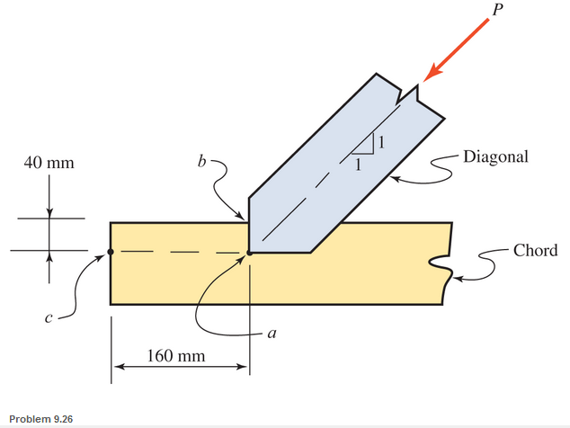
The joint between a diagonal and a chord in a timber truss is shown. The compressive force P in the diagonal s 20 kN. Determine the compressive stress in the diagonal, the bearing stress on plane ab, and the shear stress on plane ac. Both the chord and the diagonal are 150 mm by 150 mm (full nominal size) in cross section.

Learn your wayIncludes step-by-step video

Chapter 9 Solutions
Applied Statics and Strength of Materials (6th Edition)
Additional Engineering Textbook Solutions
Engineering Mechanics: Dynamics (14th Edition)
Applied Fluid Mechanics (7th Edition)
Automotive Technology: Principles, Diagnosis, and Service (5th Edition)
Thinking Like an Engineer: An Active Learning Approach (4th Edition)
Engineering Mechanics: Statics
INTERNATIONAL EDITION---Engineering Mechanics: Statics, 14th edition (SI unit)


- 3. The composite bar consists of a 20-mm diameter steel segment AB and 50-mm diameter brass end segments DA and CB. Find the stress on each segment due to the applied loads. E of steel is 200 GPa and E of brass is 101 GPa. 250mm 250mm 250mm 50mm 20mm 50mm 75KN 100KN brass steel brass D B C 75KN 100KNarrow_forwardThree round bars welded together are axially loaded as shown. Find the normal stress in each bar if P=15 kNarrow_forwardAn axial load P is applied to the rectangular bar shown. The cross-sectional area of the bar is 455 mm². Determine the normal stress perpendicular to plane AB and the shear stress parallel to plane AB if the bar is subjected to an axial load of P = 72 kN. Assume a = 36°. A a B Answers: The normal stress o = i MPa. The shear stress t = MРа.arrow_forward
- An axial load Pis applied to the rectangular bar shown. The cross-sectional area of the bar is 398 mm2. Determine the normal stress perpendicular to plane AB and the shear stress parallel to plane AB if the bar is subjected to an axial load of P = 88 kN. Assume a = 61°. a B Answers: The normal stress o = MРа. The shear stress T = i MРа.arrow_forwardDetermine the stress at the middle of rod BC in MPa for a given truss structure. If the diameter of rod BC is d=20 mm. P1= 12 kN ; P2= 18 kN ; a=3 (m); b=4 (m)arrow_forwardThe collar bearing shown is subject to a 500 kN force. 500 kN The collar is 25 mm thick. Find d and D (to the nearest mm) so that the allowable normal stress in the column collar bearing of o = 280 MPa, the allowable shear stress in the collar collar of t = 200 MPa and the allowable bearing stress between the collar and the support of ob = 70 MPa is not exceeded.arrow_forward
- 0.15m 0.75m 0.60m H 1.00m M 1.50m Figure 1: Representation of the frame system T 0.60m Figure 2: Detailing of support G 30mm 20mmarrow_forwardTo avoid interference, a link in a machine is designed so that its cross-sectional area is reduced one half at section A-B as shown below. If the thickness of the link is 50 mm, compute the maximum force P that can be applied if the maximum normal stress on section A-B is limited to 80 MPa.arrow_forward1. In the figure shown, determine the stress in the cable C if its area is 600 mm?. Neglect the weight of the bar AB. 2. In Problem 1, determine the required diameter of the pin at A if the allowable stress is 80 MPa. (double shear).arrow_forward
- Determine the resultant internal loadings acting on the cross section at B of the pipe shown. End A is subjected to a vertical force P and a horizontal force Q. Use P = 90 N and Q = 70 N. a. Determine the internal axial force (in N) in section B. b. Determine the internal shear force (in N) in section B. c. Determine the internal torque (in N-m) in section B. With FBD please thank you.arrow_forwardThe horizontal cross-section of the cast-iron standard of a vertical drilling machine has the form shown. The line of thrust of the drill passes through P. Find the greatest value the thrust may have without the tensile stress exceeding 15 MN/m2. What will be the stress along the face AB? (Cambridge) ANSWER: 17.68 kN; 11.8 MN/m2 compressive.arrow_forwardA simply supported wood beam is subjected to uniformly distributed load q. The width of the beam is 6 in, and the height is 8 in. Determine the normal stress and the shear stress at point C. Show these stresses on a sketch of a stress element at point C.arrow_forward
 Elements Of ElectromagneticsMechanical EngineeringISBN:9780190698614Author:Sadiku, Matthew N. O.Publisher:Oxford University Press
 Mechanics of Materials (10th Edition)Mechanical EngineeringISBN:9780134319650Author:Russell C. HibbelerPublisher:PEARSON
 Thermodynamics: An Engineering ApproachMechanical EngineeringISBN:9781259822674Author:Yunus A. Cengel Dr., Michael A. BolesPublisher:McGraw-Hill Education
 Control Systems EngineeringMechanical EngineeringISBN:9781118170519Author:Norman S. NisePublisher:WILEY
 Mechanics of Materials (MindTap Course List)Mechanical EngineeringISBN:9781337093347Author:Barry J. Goodno, James M. GerePublisher:Cengage Learning
 Engineering Mechanics: StaticsMechanical EngineeringISBN:9781118807330Author:James L. Meriam, L. G. Kraige, J. N. BoltonPublisher:WILEY