
Applied Statics and Strength of Materials (6th Edition)
6th Edition
ISBN: 9780133840544
Author: George F. Limbrunner, Craig D'Allaird, Leonard Spiegel
Publisher: PEARSON
expand_more
expand_more
format_list_bulleted
Videos
Textbook Question
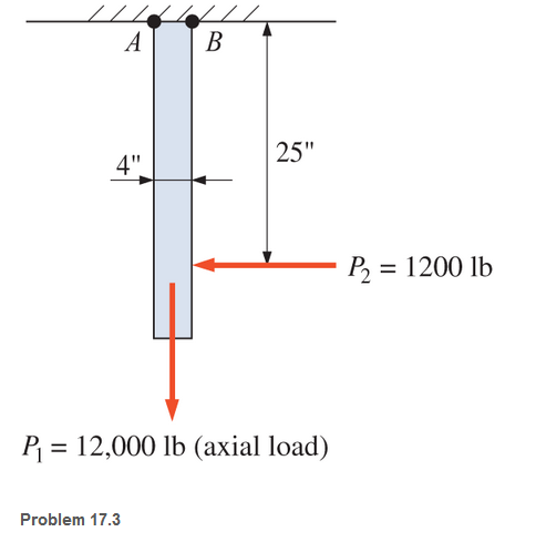
Chapter 17, Problem 17.3P
A 1-in.-by-4-in, steel bar is subjected to the loads shown. Calculate the combined stresses at points A and B.
Expert Solution & Answer
Want to see the full answer?
Check out a sample textbook solution
Students have asked these similar questions
In the figure shown if the applied force F= 24KN. Compute the stress, in MPa, in member BD.
To avoid interference, a link in a machine is designed so that its cross-sectional area is reduced one half at section A-B as shown below. If the thickness of the link is 50 mm, compute the maximum force P that can be applied if the maximum normal stress on section A-B is limited to 80 MPa.
The vertical load P acting on the wheel of a traveling crane is 13,000 lb. What is the average shear stress in the 1.25 in. diameter axle?
Chapter 17 Solutions
Applied Statics and Strength of Materials (6th Edition)
Ch. 17 - Prob. 17.1PCh. 17 - A horizontal 30-ft simple span beam is supported...Ch. 17 - A 1-in.-by-4-in, steel bar is subjected to the...Ch. 17 - A W410100 structural steel wide-flange section is...Ch. 17 - A W1272 structural steel wide-flange section is...Ch. 17 - A solid steel shaft 3 in. in diameter and 4 ft...Ch. 17 - A short compression member is subjected to a...Ch. 17 - With reference to Problem 17.7, calculate the...Ch. 17 - A section of a 51-mm-diameter standard-weight...Ch. 17 - For the pipe of Problem 17.9, compute the maximum...
Ch. 17 - A concrete pedestal is in the shape of a cube and...Ch. 17 - 17.12 For the pedestal of Problem 17.11, assume...Ch. 17 - 17.13 Rework Problem 17.11, but assume that the...Ch. 17 - A 12-in-square concrete pedestal is subjected to a...Ch. 17 - 17.15 A short compression member is subjected to a...Ch. 17 - A rectangular concrete footing, 4 ft by 8 ft in...Ch. 17 - The bending and shear stresses developed at a...Ch. 17 - Stresses developed at a point in a machine part...Ch. 17 - Calculate the principal stresses at points A and B...Ch. 17 - 17.20 Rework Problem 17.19 using P = 8000 lb and...Ch. 17 - 17.21 A 1-in.-square steel bar is subjected to an...Ch. 17 - 17.22 A bar having a cross-sectional area of 6...Ch. 17 - Rework Problem 17.22, changing the load to a...Ch. 17 - Solve Problem l7.17 using Mohr’s circle.Ch. 17 - For the elements shown in Problem 17.18, use...Ch. 17 - Solve Problem 17.19 using Mohr’s circle.Ch. 17 - In Problem 17.19, change the load to 8000 lb and...Ch. 17 - For the following computer problems, any...Ch. 17 - For the following computer problems, any...Ch. 17 - For the following computer problems, any...Ch. 17 - For the following computer problems, any...Ch. 17 - A 4-in.-by-8-in. (S4S) Douglas fir timber beam is...Ch. 17 - A horizontal flexural member (a girt) in the wall...Ch. 17 - A simply supported W1850 structural steel...Ch. 17 - A steel link in a machine is designed to avoid...Ch. 17 - 17.36 An 8-in-square (S4S) vertical timber post is...Ch. 17 - A short 3-in.-square steel bar with a...Ch. 17 - A timber member 150 mm by 250 mm (S4S) is loaded...Ch. 17 - A concrete wall 8 ft high and 3 ft thick is...Ch. 17 - 17.40 A short compression member is subjected to a...Ch. 17 - 17.41 Calculate the maximum eccentric load that...Ch. 17 - A short compression member is subjected to two...Ch. 17 - 17.43 Calculate the force P that may be applied to...Ch. 17 - 17.44 A load of 1000 lb is supported on a...Ch. 17 - 17.45 A short compression member is subjected to...Ch. 17 - 17.46 A structural steel wide-flange section is...Ch. 17 - 17.47 A cast-iron frame for a piece of industrial...Ch. 17 - 17.48 The assembly shown is used in a machine. It...Ch. 17 - 17.49 A 50-mm-diameter solid steel shaft is...Ch. 17 - An element of a machine member is subjected to the...Ch. 17 - 17.51 A short-span cantilever built-up beam has...Ch. 17 - Solve Problem 17.50 using Mohr’s circle.Ch. 17 - 17.53 A cantilever beam is subjected to an...Ch. 17 - A 6-in.-diameter solid shaft is subjected to a...Ch. 17 - Rework parts (b) and (c) of Example 17.7 using...
Knowledge Booster


Learn more about
Need a deep-dive on the concept behind this application? Look no further. Learn more about this topic, mechanical-engineering and related others by exploring similar questions and additional content below.Similar questions
- Calculate the maximum and minimum normal stresses experienced by the lever indicated in the image.arrow_forwardA bar having a cross-section areas of 700mm2 is subjected to axial loads at the positions indicated,find the value of stress in the segment QRarrow_forwardAssume that the axial load P applied to the lap joint is distributed equally among the three 20-mm-diameter rivets. What is the maximum load P that can be applied if the allowable stresses are 40 MPa for shear in rivets, 90 MPa for bearing between a plate and a rivet, and 120 MPa for tension in the plates?arrow_forward
- Calculate the normal stresses at points A and B of the bracket caused by the 30-kN force.arrow_forward3. Calculate the contact stress between a 100-mm- diameter steel ball weighing 500 g sitting on a hardened steel surface plate.arrow_forwardCalculate the normal stress (in Pa) at point A of the bracket caused by the 11023 N force.arrow_forward
- A 6" diameter pulley attached to a 1" diameter shaft of 2" length is supporting a load of 2000 lb. Determine the location of the highest stresses in the 1" diameter shaft and calculate principal stresses at that point.arrow_forwardA 15 in diameter rod is subjected to an axial tensile load of 45 kips. Compute. a. The normal stress developed on an inclined plane at an angle of 60° with the cross section of the rod. b. The maximum normal stress developed in the rod.arrow_forwardA circular rod with a diameter of 40.0 mm has a groove cut to a diameter of 35 mm. A full radius of 3.0 mm is produced at the bottom of the groove. Compute the maximum stress in the rod when an axial tensile force of 46 kN is applied.arrow_forward
- Calculate the smallest area of each cable if the stress is not to exceed 76 000 KPa in bronze and 118 MPa in steel if a homogeneous 778 000 g bar AB is supported at either end by a cable.arrow_forwardThe four bars shown have the same cross-sectional area. For the given loadings, show that (a) the maximum compressive stresses are in the ratio 4:5:7:9, (b) the maximum tensile stresses are in the ratio 2:3:5:3. (Note: the cross section of the triangular bar is an equilateral triangle.)arrow_forwardA steel rod 20 mm in diameter passes centrally through a steel tube of 25 mm internal diameter and 30 mm external diameter. The tube is 800 mm long and is closed by rigid washers of negligible thickness which are fastened by nuts threaded on the rod. The nuts are tightened until the compressive load on the tube is 20 kN. Calculate the stresses in the tube and the rod.Find the increase in these stresses when one nut is tightened by one-quarter of a turn relative to the other. There are 4 threads per 10 mm. Take E = 2 x 10⁵ N/mm2.arrow_forward
arrow_back_ios
SEE MORE QUESTIONS
arrow_forward_ios
Recommended textbooks for you
 Elements Of ElectromagneticsMechanical EngineeringISBN:9780190698614Author:Sadiku, Matthew N. O.Publisher:Oxford University Press
 Mechanics of Materials (10th Edition)Mechanical EngineeringISBN:9780134319650Author:Russell C. HibbelerPublisher:PEARSON
 Thermodynamics: An Engineering ApproachMechanical EngineeringISBN:9781259822674Author:Yunus A. Cengel Dr., Michael A. BolesPublisher:McGraw-Hill Education
 Control Systems EngineeringMechanical EngineeringISBN:9781118170519Author:Norman S. NisePublisher:WILEY
 Mechanics of Materials (MindTap Course List)Mechanical EngineeringISBN:9781337093347Author:Barry J. Goodno, James M. GerePublisher:Cengage Learning
 Engineering Mechanics: StaticsMechanical EngineeringISBN:9781118807330Author:James L. Meriam, L. G. Kraige, J. N. BoltonPublisher:WILEY
Elements Of Electromagnetics
Mechanical Engineering
ISBN:9780190698614
Author:Sadiku, Matthew N. O.
Publisher:Oxford University Press
Mechanics of Materials (10th Edition)
Mechanical Engineering
ISBN:9780134319650
Author:Russell C. Hibbeler
Publisher:PEARSON
Thermodynamics: An Engineering Approach
Mechanical Engineering
ISBN:9781259822674
Author:Yunus A. Cengel Dr., Michael A. Boles
Publisher:McGraw-Hill Education
Control Systems Engineering
Mechanical Engineering
ISBN:9781118170519
Author:Norman S. Nise
Publisher:WILEY
Mechanics of Materials (MindTap Course List)
Mechanical Engineering
ISBN:9781337093347
Author:Barry J. Goodno, James M. Gere
Publisher:Cengage Learning
Engineering Mechanics: Statics
Mechanical Engineering
ISBN:9781118807330
Author:James L. Meriam, L. G. Kraige, J. N. Bolton
Publisher:WILEY
Differences between Temporary Joining and Permanent Joining.; Author: Academic Gain Tutorials;https://www.youtube.com/watch?v=PTr8QZhgXyg;License: Standard Youtube License