
Applied Statics and Strength of Materials (6th Edition)
6th Edition
ISBN: 9780133840544
Author: George F. Limbrunner, Craig D'Allaird, Leonard Spiegel
Publisher: PEARSON
expand_more
expand_more
format_list_bulleted
Videos
Textbook Question
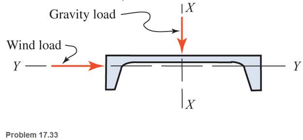
Chapter 17, Problem 17.33SP
A horizontal flexural member (a girt) in the wall of a prefabricated metal building is composed of a
Expert Solution & Answer
Want to see the full answer?
Check out a sample textbook solution
Students have asked these similar questions
A long retaining wall is braced by wood shores set at an angle of 308 and supported by concrete thrust blocks, as shown in the first part of thefigure. The shores are evenly spaced at 3 m apart. For analysis purposes, the wall and shores are idealized as shown in the second part of the figure.Note that the base of the wall and both ends of the shores are assumed to be pinned. The pressure of the soil against the wall is assumed to be triangularly distributed, and the resultant force acting on a 3-meter length of the walls is F =190 kN. If each shore has a 150 mm 3150 mm square cross section, what is the compressive stress σc in the shores?
Question 5
Find the supportive force system for the cantilever beam shown pinned at C. Given data: Point load,
Not yet answered
P=380 N and distributed load, w=80 N/m.
Marked out of 5.00
on
7 m
2 m
A
5 m-
5 m-
Supportive force system
Ax=
Ay=
Сх-
N
Су-
By=
N
A small balcony constructed of wood issupported by three identical cantilever beams (seefigure). Each beam has length L1 = 2.1m, width b,and height h = 4b/3. The dimensions of the balconyfloor are L1 XL2, where L2 = 2.5 m. The designload is 5.5 kPa acting over the entire floor area.(This load accounts for all loads except the weightsof the cantilever beams, which have a weight densityΥ = 5.5 kN/m3.) The allowable bending stress in thecantilevers is 15 MPa.Assuming that the middle cantilever supports50% of the load and each outer cantilever supports25% of the load, determine the required dimensions band h.
Chapter 17 Solutions
Applied Statics and Strength of Materials (6th Edition)
Ch. 17 - Prob. 17.1PCh. 17 - A horizontal 30-ft simple span beam is supported...Ch. 17 - A 1-in.-by-4-in, steel bar is subjected to the...Ch. 17 - A W410100 structural steel wide-flange section is...Ch. 17 - A W1272 structural steel wide-flange section is...Ch. 17 - A solid steel shaft 3 in. in diameter and 4 ft...Ch. 17 - A short compression member is subjected to a...Ch. 17 - With reference to Problem 17.7, calculate the...Ch. 17 - A section of a 51-mm-diameter standard-weight...Ch. 17 - For the pipe of Problem 17.9, compute the maximum...
Ch. 17 - A concrete pedestal is in the shape of a cube and...Ch. 17 - 17.12 For the pedestal of Problem 17.11, assume...Ch. 17 - 17.13 Rework Problem 17.11, but assume that the...Ch. 17 - A 12-in-square concrete pedestal is subjected to a...Ch. 17 - 17.15 A short compression member is subjected to a...Ch. 17 - A rectangular concrete footing, 4 ft by 8 ft in...Ch. 17 - The bending and shear stresses developed at a...Ch. 17 - Stresses developed at a point in a machine part...Ch. 17 - Calculate the principal stresses at points A and B...Ch. 17 - 17.20 Rework Problem 17.19 using P = 8000 lb and...Ch. 17 - 17.21 A 1-in.-square steel bar is subjected to an...Ch. 17 - 17.22 A bar having a cross-sectional area of 6...Ch. 17 - Rework Problem 17.22, changing the load to a...Ch. 17 - Solve Problem l7.17 using Mohr’s circle.Ch. 17 - For the elements shown in Problem 17.18, use...Ch. 17 - Solve Problem 17.19 using Mohr’s circle.Ch. 17 - In Problem 17.19, change the load to 8000 lb and...Ch. 17 - For the following computer problems, any...Ch. 17 - For the following computer problems, any...Ch. 17 - For the following computer problems, any...Ch. 17 - For the following computer problems, any...Ch. 17 - A 4-in.-by-8-in. (S4S) Douglas fir timber beam is...Ch. 17 - A horizontal flexural member (a girt) in the wall...Ch. 17 - A simply supported W1850 structural steel...Ch. 17 - A steel link in a machine is designed to avoid...Ch. 17 - 17.36 An 8-in-square (S4S) vertical timber post is...Ch. 17 - A short 3-in.-square steel bar with a...Ch. 17 - A timber member 150 mm by 250 mm (S4S) is loaded...Ch. 17 - A concrete wall 8 ft high and 3 ft thick is...Ch. 17 - 17.40 A short compression member is subjected to a...Ch. 17 - 17.41 Calculate the maximum eccentric load that...Ch. 17 - A short compression member is subjected to two...Ch. 17 - 17.43 Calculate the force P that may be applied to...Ch. 17 - 17.44 A load of 1000 lb is supported on a...Ch. 17 - 17.45 A short compression member is subjected to...Ch. 17 - 17.46 A structural steel wide-flange section is...Ch. 17 - 17.47 A cast-iron frame for a piece of industrial...Ch. 17 - 17.48 The assembly shown is used in a machine. It...Ch. 17 - 17.49 A 50-mm-diameter solid steel shaft is...Ch. 17 - An element of a machine member is subjected to the...Ch. 17 - 17.51 A short-span cantilever built-up beam has...Ch. 17 - Solve Problem 17.50 using Mohr’s circle.Ch. 17 - 17.53 A cantilever beam is subjected to an...Ch. 17 - A 6-in.-diameter solid shaft is subjected to a...Ch. 17 - Rework parts (b) and (c) of Example 17.7 using...
Knowledge Booster


Learn more about
Need a deep-dive on the concept behind this application? Look no further. Learn more about this topic, mechanical-engineering and related others by exploring similar questions and additional content below.Similar questions
- A cylindrical brick chimney of height H weighs w = 825 lb/ft of height (see figure). The inner and outer diameters are d1= 3 ft and d2= 4 ft, respectively. The wind pressure against the side of the chimney is p = 10 lb/ft2 of projected area. Determine the maximum height H if there is to be no tension in the brickwork.arrow_forwardDetermine the maximum tensile and compressive stresses developed in the overhanging beam that is loaded and has the cross- sectional properties as shown. 1600 lb 4000 lb 2 in N.A. 6 in 6 ft R I- 90 in 6 ft tensile stress = 3, 840 psi and compressive stress = 7, 680 psi tensile stress = 1, 280 psi and compressive stress = 2,560 psi tensile stress = 7, 680 psi and compressive stress = 3, 840 psi tensile stress = 7, 680 psi and compressive stress = 2, 560 psiarrow_forwardThe structure in the sketch below consists of the two members ABC and CDE which are pin- connected at point C. The complete structure is supported by a weightless link at B and a fixed support at E. The link is perpendicular to part BCDE and pin-connected to the support at the bottom. The distributed loading acts perpendicular to the inclined part AB. The figure is not to scale. 600 N/ m A 900N 0.5m E C -1.3т- * 1m - 1m 1.2m Calculate the support reactions that develop on the frame at points B and E. Interpret your final answers on a separate complete free-body diagram of the structure ABCDE. B,arrow_forward
- A new art exhibit featuring mobile works is going up in the Norwalk, CA area. One art work is shown in the figure below. A 105 N uniform beam is pinned to the ground by a pivot. The beam is supported by a cable (attached 3/5 from the bottom of the beam) to allow for each of the shoes to hang freely. Each individual shoe has a weight of 7.5 N. 10 WALL FLOR (a) ( If one shoe is attached 1/7 of the way up the beam and another shoe is attached 5/8 of the way up the beam, with e, = 70.1° and e, 30.1°, what is the tension in the cable, in newtons? %3! %3D (b) What is the x-component of the force, in newtons, that the pivot exerts on the bottom of the beam? (c) O What is the y-component of the force, in newtons, that the pivot exerts on the bottom of the beam?arrow_forwardTypically, an aircraft wing is supported by a single structural spar attached to the main fuselage at the wing root as shown. This arrangement can be idealized as a cantilever beam with a loading distribution characterizing wing pressure. In general, holes are introduced to the structural members to reduce the overall weight of the wing (observe the rib sections shown in B). For the idealized beam arrangement (shown in the C), assume that the cross section of the spar is uniform and has a rectangular cross section (2" x 16"). The material is 2016-T6 Aluminum. If four 7" diameter holes are introduced to the beam (as shown in C, below), what is the maximum increase in normal stress? Ignore the effect of transverse shear. (A) (C) Wing Root (Assumed Fixed) 80 lb/in 1.8' 1.8' (B) 1.8' 9' Wing Root + 1.8' W Wing Tip Fuel Tank Wing Tip (Assumed Free)arrow_forwardA new art exhibit featuring mobile works is going up in the Holland, MI, area. One piece is shown in the figure. The 155-N uniform beam is pinned to the ground by a pivot. The beam is supported by a cable (attached to the center of the beam) to allow for each of the shoes to hang freely. Each individual shoe has a weight of 9.5-N. If one shoe is attached two-fifths of the way up the beam and another shoe is attached and three-fifths of the way up the beam, with θc = 16.5° and θb = 33.6° as shown in the figure, what is the tension in the cable, in newtons? What is the x-component of the force, in newtons, that the pivot exerts on the bottom of the beam? Use the coordinate system specified in the figure. What is the y-component of the force, in newtons, that the hinge exerts on the bottom of the beam? Use the coordinate system specified in the figure.arrow_forward
- A simply supported beam, 3 in wide by 3 in deep, carries a uniformly distributed load of 80 lb/ft over its entire length. What is the maximum length of the beam if the flexural stress is limited to 3000 psi? 80 Ib/ft R1 R2arrow_forwardThe bending moment diagram (B.M.D) of the base of (2.5x2.5)m dimensions opening box culvert (shown below), Find the live load acting on it. Make use: the thickness of the roof and wall is 0.25m, 9 s=18 Kn/m², 9c=25Kn/m³, Ho=1.5m and the impact factor is (1.3). 57 kn.m 55.7 kn.m 57 kn.marrow_forwardA simply supported beam of span 3.0 m has a cross-section 120 mm × 180 mm. If the permissible stress in the material of the beam is 10 N/mm^2, determine maximum udl it can carry.arrow_forward
- Picture given below; There is a uniformly distributed load on the beam, which is made of Al2010 (T4) alloy T-profile and is connected to the "A" sliding bearing with "B" joint fixed support. Safe compression and tensile normal stress of the beam is Gemn=100 MPa. q=23 kN/m C-C Kesiti + 15 | 18 | 15 q=23 kN/m A유 30 cm 100 cm 150 cm 16 KİRİŞ T- PROFİLİ 74 Ød MAFSAL PİMİ Ölçüler mm dir. 104 S-1) Calculate the support reactions by drawing the SCD of the beam. S-2) The beam; a) Draw the shear force diagram, b) Moment diagram and determine the maximum moment. S-3) Find the x and y axis coordinates of the center of gravity of the cross-sectional area of the beam whose T-profile dimensions are given. S-4) Find the moments of inertia with respect to the vertical and horizontal axes passing through the center of gravity of the T-profile cross-section area. S-5) Find the tensile and compression stresses caused by bending on the beam with T-profile and check the safe carrying condition of this…arrow_forwardThe wood beam supports loads of w = 410 Ib/ft and P = 840 lb on span lengths of LAB = 10.8 ft, LBC = 5.4 ft, and LcD= 5.4 ft. The beam cross section has dimensions of bq = 1.9 in., dq = 5.7 in., b2 = 5.0 in., and d2 = 14.95 in. Determine the magnitude and location of: (a) the maximum horizontal shear stress in the beam. (b) the maximum tensile bending stress in the beam. %3D %3D P d d2 В C D LAB LBC LCD b2 Answer: (a) Tmax psi (b) Omax psiarrow_forwardOur University wants to construct a swimming pool inside the campus, for which they are in need of a diving board which must be one end fixed and other is free. That is to be made up of flexible composite material. The maximum allowable load at free end is 700 kN. The length of the cantilever beam is 1.6 m. The cross section of the beam is a hollow rectangular section. Outer rectangle of size 140 mm breadth and 110 mm depth with the overall wall thickness of 12 mm. Find the deflection at the free end and maximum slope in beam by neglecting self-weight of the diving board. Take E as 170 GPa.arrow_forward
arrow_back_ios
SEE MORE QUESTIONS
arrow_forward_ios
Recommended textbooks for you
 Mechanics of Materials (MindTap Course List)Mechanical EngineeringISBN:9781337093347Author:Barry J. Goodno, James M. GerePublisher:Cengage Learning
Mechanics of Materials (MindTap Course List)
Mechanical Engineering
ISBN:9781337093347
Author:Barry J. Goodno, James M. Gere
Publisher:Cengage Learning
Mechanics of Materials Lecture: Beam Design; Author: UWMC Engineering;https://www.youtube.com/watch?v=-wVs5pvQPm4;License: Standard Youtube License