
Videos
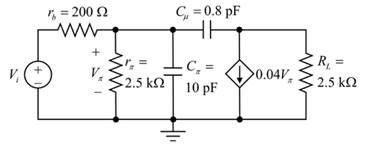
Consider the circuit in Figure P7.49. Calculate the impedance seen by thesignalsource
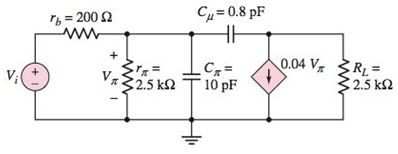
Figure P7.49
a.
The impedance seen by the signal source V1 at the given frequency.
Answer to Problem 7.49P
The impedance
Explanation of Solution
Given:
The circuit diagram is given as:
The given data:
The value of the resistor
The value of the resistor
The value of the resistor
The value of the capacitor
The value of the capacitor
The value of the trans-conductance
The frequency,
Evaluating the miller capacitance:
Substituting the known values:
Evaluating the value of the capacitance
Substituting the known values to the above equation:
Redrawing the given diagram after some changes:
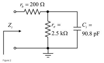
Evaluaating the impedance
Since,
Evaluating the impedance
Substitute
Hence, the impedance
b.
The impedance seen by the signal source V1 at the given frequency.
Answer to Problem 7.49P
The impedance
Explanation of Solution
Given:
The circuit diagram is given as:

The given data:
The value of the resistor
The value of the resistor
The value of the resistor
The value of the capacitor
The value of the capacitor
The value of the trans-conductance
The frequency
Consider the following data
Calculate the impedance
Substitute
Therefore , the impedance
c.
The impedance seen by the signal source V1 at the given frequency.
Answer to Problem 7.49P
The impedance
Explanation of Solution
Given:
The circuit diagram is given as:

The given data:
The value of the resistor
The value of the resistor
The value of the resistor
The value of the capacitor
The value of the capacitor
The value of the trans-conductance
The frequency
Consider the following data:
Calculate the impedance
Substitute
Therefore, the impedance
c.
The impedance seen by the signal source V1 at the given frequency.
Answer to Problem 7.49P
the impedance
Explanation of Solution
Given:
The circuit diagram is given as:

The given data:
The value of the resistor
The value of the resistor
The value of the resistor
The value of the capacitor
The value of the capacitor
The value of the trans-conductance
The frequency
Consider the following data:
Calculate the impedance
Substitute
Therefore, the impedance
Want to see more full solutions like this?
Chapter 7 Solutions
MICROELECT. CIRCUIT ANALYSIS&DESIGN (LL)


- 1) Suppose you have a sinusoidal input signal and wish at the output the signal should be same (in phase) as input signal but amplified then which circuit should you use? & WHY?? Draw the circuit diagram you would use.arrow_forwardWrite the general voltage equation for a 250-Hz source whose peak voltage is 300 V.arrow_forward4. The average power consumed by a resistance is equal to .. in non- .... ... sinusoidal input signal. *arrow_forward
- Example-7.5 A step-up chopper has input voltage of 220 V and output voltage of 660 V. If conducting time of thyristor-chopper is 100 μs, compute the pulse width of output voltage. In case out-voltage pulse width is halved for constant frequency operation, find the average value of new put voltage.arrow_forwardA step-down chopper is to be used to supply power from a 600-V overhead wire to the commutator motor on a trolley bus. The motor may be mod- eled as a generated direct voltage in series with a resistance of 0.2 and an inductance of 25 mH. The frequency of the chopper is set at 500 Hz. (a) When the bus is stopped, what should be the ON time of the chopper to provide a motor current of 150 A? (b) What is the maximum possible generated voltage of the motor for which a current of 150 A can be supplied? (c) What is the average value of the supply current for the conditions of (a) and (b)? បទៅនឹងរស់របស (d) If the motor current is to be continuous, what should be its minimum. value?arrow_forwardFacts A clipper is a device that removes either the positive half (top half) or negative half (bottom half), or both positive and negative halves of the input AC signal. In other words, a clipper is a device that limits the positive amplitude or negative amplitude or both positive and negative amplitudes of the input AC signal. In some cases, a clipper removes a small portion of the positive half cycle or negative half cycle or both positive and negative half cycles. In the below circuit diagram, the positive half cycles are removed by using the series positive clipper. Question: In your own opinion. Why do we need to clip a certain amount of voltage in positive or negative or on both sides? What is the benefit of that in our devices or circuits in doing such thing?arrow_forward
- The sinusoidal voltage trace displayed by the CRO, the time/cm switch is on 50 µs/cm and the volt/cm switch is on 20 V/cm. The width of one complete cycle is 3.6 cm and the peak to peak height is 5.8 cm. Determine the following: The frequency is = The peak to peak voltage is = The amplitude is = The R.M.S voltage is =arrow_forwardAn AC waveform is shown in figure B18. 10 20 Figure B18 For the above waveform, determine a. Peak-to-peak voltage b. Time period c. Frequency For the above waveform, determine a. Peak Factor b. Form Factorarrow_forwardAn inductor is attached to an AC voltage source. Which change will result in a halving of the current?A. Halving the voltage and doubling the frequencyB. Doubling the frequencyC. Halving the frequencyD. Doubling the voltage and halving the frequencyarrow_forward
- A phase modulator has kp= 2.8rad/V. What rms voltage of a sine wave causes a peak phase deviation of 74°? Determine the peak phase deviation for a PM modulator with deviation sensitivity K = 3.8 rad/V and a modulating signal vm= 12 sin(2π1000t).arrow_forwardit is the fractional value of an AC quantity through which the .6 * .AC quantity has advanced or delayed from the reference point frequency period Peak-to-peak value Phase different phase Oarrow_forwardFor the below sinusoidal voltage trace displayed by the CRO, the time/cm switch is on 0.2ms/cm and the volt/cm switch is on 1 V/cm. a) the frequency will be Hz b) the r.m.s value will be In CRO the beam can also be shifted vertically by applving a suitable DC voltage to thearrow_forward
 Introductory Circuit Analysis (13th Edition)Electrical EngineeringISBN:9780133923605Author:Robert L. BoylestadPublisher:PEARSON
 Delmar's Standard Textbook Of ElectricityElectrical EngineeringISBN:9781337900348Author:Stephen L. HermanPublisher:Cengage Learning
 Programmable Logic ControllersElectrical EngineeringISBN:9780073373843Author:Frank D. PetruzellaPublisher:McGraw-Hill Education
 Fundamentals of Electric CircuitsElectrical EngineeringISBN:9780078028229Author:Charles K Alexander, Matthew SadikuPublisher:McGraw-Hill Education
 Electric Circuits. (11th Edition)Electrical EngineeringISBN:9780134746968Author:James W. Nilsson, Susan RiedelPublisher:PEARSON
 Engineering ElectromagneticsElectrical EngineeringISBN:9780078028151Author:Hayt, William H. (william Hart), Jr, BUCK, John A.Publisher:Mcgraw-hill Education,