
Mechanics of Materials (10th Edition)
10th Edition
ISBN: 9780134319650
Author: Russell C. Hibbeler
Publisher: PEARSON
expand_more
expand_more
format_list_bulleted
Videos
Textbook Question
thumb_up100%
Chapter 3.4, Problem 3.14P
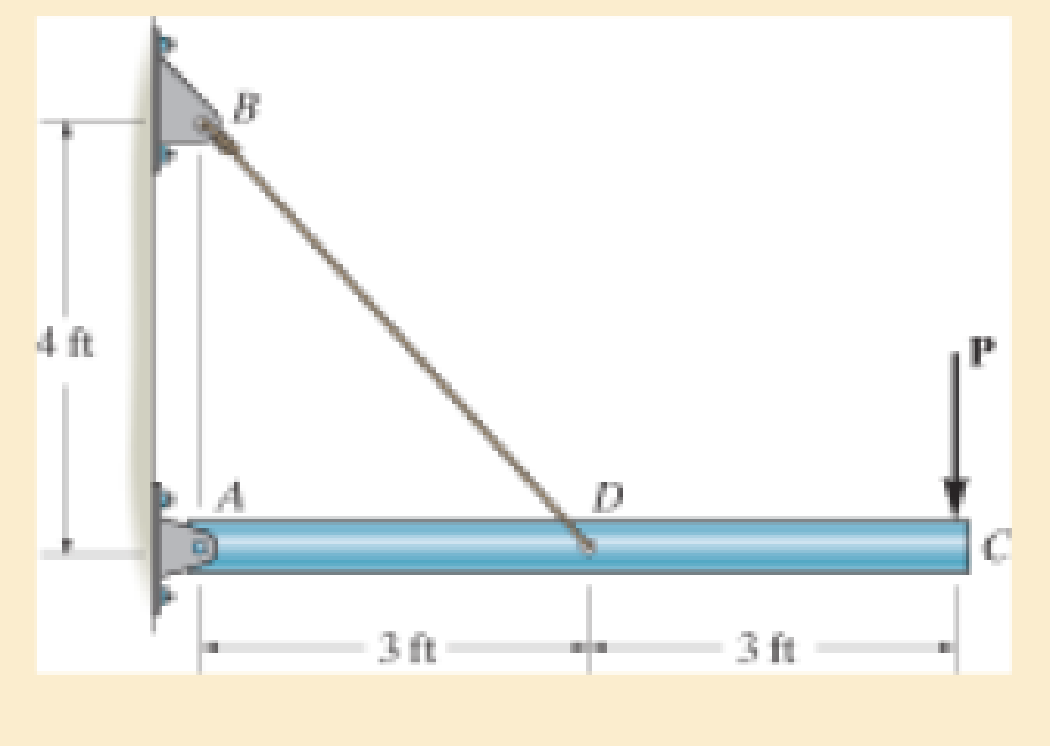
The rigid pipe is supported by a pin at A and an A-36 steel guy wire BD. If the wire has a diameter of 0.25 in., determine how much it stretches when a load of P = 600 lb acts on the pipe.
Expert Solution & Answer

Trending nowThis is a popular solution!

Learn your wayIncludes step-by-step video

schedule06:16
Students have asked these similar questions
The strut is supported by a pin at C and an A-36 steel guy wire AB. If the wire has a diameter of 1,2 m , determine how much it stretches when the distributed load acts on the strut.
The pole is supported by a pin at C and an A-36 steel guy wire AB. If the wire has a diameter of 0.2 in., determine how much it stretches when a horizontal force of 2.5 kip acts on the pole.
The rigid pipe is supported by a pin at A and an A-36 guy wire BD. The wire has a diameter of 0.27 in.
Determine the load P if the end C is displaced 0.075 in. downward.
Chapter 3 Solutions
Mechanics of Materials (10th Edition)
Ch. 3.4 - Define a homogeneous material.Ch. 3.4 - Indicate the points on the stress-strain diagram...Ch. 3.4 - Define the modulus of elasticity E.Ch. 3.4 - At room temperature, mild steel is a ductile...Ch. 3.4 - Engineering stress and strain are calculated using...Ch. 3.4 - As the temperature increases the modulus of...Ch. 3.4 - A 100-mm-long rod has a diameter of 15 mm. If an...Ch. 3.4 - A bar has a length of 8 in. and cross-sectional...Ch. 3.4 - A 10-mm-diameter rod has a modulus of elasticity...Ch. 3.4 - The material for the 50-mm-long specimen has the...
Ch. 3.4 - The material for the 50-mm-long specimen has the...Ch. 3.4 - If the elongation of wire BC is 0.2 mm after the...Ch. 3.4 - A tension test was performed on a steel specimen...Ch. 3.4 - Data taken from a stress-strain test for a ceramic...Ch. 3.4 - Data taken from a stress-strain test for a ceramic...Ch. 3.4 - The stress-strain diagram for a steel alloy having...Ch. 3.4 - The stress-strain diagram for a steel alloy having...Ch. 3.4 - The stress-strain diagram for a steel alloy having...Ch. 3.4 - The rigid beam is supported by a pin at C and an...Ch. 3.4 - The rigid beam is supported by a pin at C and an...Ch. 3.4 - Acetal plastic has a stress-strain diagram as...Ch. 3.4 - The stress-strain diagram for an aluminum alloy...Ch. 3.4 - The stress-strain diagram for an aluminum alloy...Ch. 3.4 - The stress-strain diagram for an aluminum alloy...Ch. 3.4 - A bar having a length of 5 in. and cross-sectional...Ch. 3.4 - The rigid pipe is supported by a pin at A and an...Ch. 3.4 - The rigid pipe is supported by a pin at A and an...Ch. 3.4 - Direct tension indicators are sometimes used...Ch. 3.4 - The rigid beam is supported by a pin at C and an...Ch. 3.4 - The rigid beam is supported by a pin at C and an...Ch. 3.4 - The stress-strain diagram for a bone is shown, and...Ch. 3.4 - The stress-strain diagram for a bone is shown and...Ch. 3.4 - The two bars are made of a material that has the...Ch. 3.4 - The two bars are made of a material that has the...Ch. 3.4 - The pole is supported by a pin at C and an A-36...Ch. 3.4 - The bar DA is rigid and is originally held in the...Ch. 3.7 - A 100-mm-long rod has a diameter of 15 mm. If an...Ch. 3.7 - A solid circular rod that is 600 mm long and 20 mm...Ch. 3.7 - A 20-mm-wide block is firmly bonded to rigid...Ch. 3.7 - A 20-mm-wide block is bonded to rigid plates at...Ch. 3.7 - The acrylic plastic rod is 200 mm long and 15 mm...Ch. 3.7 - The plug has a diameter of 30 mm and fits within a...Ch. 3.7 - The elastic portion of the stress-strain diagram...Ch. 3.7 - The elastic portion of the stress-strain diagram...Ch. 3.7 - The brake pads for a bicycle tire are made of...Ch. 3.7 - The lap joint is connected together using a 1.25...Ch. 3.7 - The lap joint is connected together using a 1.25...Ch. 3.7 - The rubber block is subjected to an elongation of...Ch. 3.7 - The shear stress-strain diagram for an alloy is...Ch. 3.7 - A shear spring is made from two blocks of rubber,...Ch. 3 - The elastic portion of the tension stress-strain...Ch. 3 - The elastic portion of the tension stress-strain...Ch. 3 - The rigid beam rests in the horizontal position on...Ch. 3 - The wires each have a diameter of 12 in., length...Ch. 3 - The wires each have a diameter of 12 in., length...Ch. 3 - diameter steel bolts. If the clamping force in...Ch. 3 - The stress-strain diagram for polyethylene, which...Ch. 3 - The pipe with two rigid caps attached to its ends...Ch. 3 - The 8-mm-diameter bolt is made of an aluminum...Ch. 3 - An acetal polymer block is fixed to the rigid...
Additional Engineering Textbook Solutions
Find more solutions based on key concepts
13.1 through 13.6 Calculate the reactions at points A and B for the beams shown.
Applied Statics and Strength of Materials (6th Edition)
The bulk head AD Is subjected to both water and soil-backfill pressures. Assuming AD is pinned to the ground at...
INTERNATIONAL EDITION---Engineering Mechanics: Statics, 14th edition (SI unit)
If the block is held in the equilibrium position shown, determine the mass of the block at D.
Engineering Mechanics: Statics
Determine the reactions at the supports. Prob. 4-6
Statics and Mechanics of Materials (5th Edition)
1. In 2001 , the first iPodTM by Apple had a rated battery life of 10 hours (h) to run audio files. The 6th mod...
Thinking Like an Engineer: An Active Learning Approach (3rd Edition)
ICA 7-1
Express the following values using scientific notation, engineering notation, and using an appropriate ...
Thinking Like an Engineer: An Active Learning Approach (4th Edition)
Knowledge Booster


Learn more about
Need a deep-dive on the concept behind this application? Look no further. Learn more about this topic, mechanical-engineering and related others by exploring similar questions and additional content below.Similar questions
- The bolt AB in (Figure 1) has a diameter of 18 mm and passes through a sleeve that has an inner diameter of 42 mm and an outer diameter of 52 mm. The bolt and sleeve are made of A-36 steel and are secured to the rigid brackets as shown. If the bolt length is 220 mm and the sleeve length is 200 mm, determine the tension in the bolt when a force of 50 kN is applied to the brackets.arrow_forward3. At temperature T₁, the two rigidly connected rods just fit the rigid supports. If both sections are identical except for the diameter, prove that the following equations are true when temperature rises to T₂. a. F= b. OAB C. OBC A x(T₂-T₁)лd²E 20 x(T₂-T₁)E 5 9x(T₂-T₁)E 5 -1/2- d B 1/12- d Carrow_forwardThe two steel shafts (1) and (2) each Ø10 should be connected to each other with the help of the sleeve (3) (Øinner = 10, Øoutside = 15) also made of steel and two rivets at the points shown. The shaft (1) is firmly clamped on the left- hand side, the force F = 100 N acts on shaft 2 in the direction of the arrow. How are the brass round rivets to be dimensioned so that a safety of the coupling against failure of S = 10 is achieved? hole for rivets 1 F 3 a) What type of connection does a riveted connection have? b) What type of load does the rivet have? c) What is the diameter of the rivets? d) Which areas of the rivet are loaded? (Draw in figure and formula) e) Dimension the rivetarrow_forward
- If the allowable tensile stress for the bar is 1st2allow = 21 ksi, and the allowable shear stress for the pin is tallow = 12 ksi, determine the diameter of the pin so that the load P will be a maximum. What is this load? Assumethe hole in the bar has the same diameter d as the pin. Take t = 1 4 in. and w = 2 in.arrow_forwardProblem #2: The strut is by a pin at C and a A-36 steel guy wire AB (E = 200 GPa). If the wire has a diameter 5 mm, determine how much it stretches when the distributed load acts on the strut. A 60° 3.4 kN/m В 2.7 m Solve only by using this Donot nse equation &= AS'-AS AEarrow_forwardQ1/ The yoke-and-rod connection is subjected to the load shown below. Determine to the nearest one millimeter (1) the required diameter of the steel pin A between the members and (2) the required diameter of the rods. Assume that the normal failure stress is 400 MPa and the shear failure stress is 240 MPa . Use factor of safety against failure in normal stress of 2.0 and factor of safety against failure in shear stress of 3.0. di 15 kN di 15 kNarrow_forward
- For the connection shown, determine the average shear stress in the 0.75-in.-diameter bolts if the load is P = 64 kips.arrow_forwardPrior to the application of the P = 120 kip load, the gap between C and the rigid wall at D was as depicted as below. Determine the support reaction at D (in kip) after force P has been applied. The assembly is made of solid cylinders: AB is Stainless 304 steel alloy, and BC is 6061-T6 aluminum alloy.arrow_forwardThe bar is connected to the support using a pin having a diameter of d =lin. If the allowable tensile stress for the bar is (o,)low = 20ksi , and the allowable bearing stress between the pin and the bar is (0,)allow = 30ksi , determine the dimension w and t so that the gross area of the cross section is wt = 2in² and the load P is a maximum. What is this maximum load? Assume the hole in the bar has the same diameter as the pin. (Hint: Use the prjjected area whenj calculating the bearing stress.) t d w/2 w/2arrow_forward
- 5 - The ring supports the 1000-N load and is held in position by the two cables attached to vertical walls . Find the tensions T1 and T2 by at least two different ways . 1C00 Narrow_forwardFor the below assembly, if the gap between C and the rigid wall at D is initially 0.1 mm, determine the support reaction at poire A after the load (P-220 kN) is applied. The two parts of the assembly a made of A36 steel with E-200 GP -600 mm 50 mm B 600 mm 25 mm 0.1 mmarrow_forwardThe rigid beam is supported by a pin at C and an A-36 steel guy wire AB. If the wire has a diameter of 0.2 in., determine the distributed load w if the end B is displaced 0.75 in. downward.arrow_forward
arrow_back_ios
SEE MORE QUESTIONS
arrow_forward_ios
Recommended textbooks for you
 Elements Of ElectromagneticsMechanical EngineeringISBN:9780190698614Author:Sadiku, Matthew N. O.Publisher:Oxford University Press
 Mechanics of Materials (10th Edition)Mechanical EngineeringISBN:9780134319650Author:Russell C. HibbelerPublisher:PEARSON
 Thermodynamics: An Engineering ApproachMechanical EngineeringISBN:9781259822674Author:Yunus A. Cengel Dr., Michael A. BolesPublisher:McGraw-Hill Education
 Control Systems EngineeringMechanical EngineeringISBN:9781118170519Author:Norman S. NisePublisher:WILEY
 Mechanics of Materials (MindTap Course List)Mechanical EngineeringISBN:9781337093347Author:Barry J. Goodno, James M. GerePublisher:Cengage Learning
 Engineering Mechanics: StaticsMechanical EngineeringISBN:9781118807330Author:James L. Meriam, L. G. Kraige, J. N. BoltonPublisher:WILEY
Elements Of Electromagnetics
Mechanical Engineering
ISBN:9780190698614
Author:Sadiku, Matthew N. O.
Publisher:Oxford University Press
Mechanics of Materials (10th Edition)
Mechanical Engineering
ISBN:9780134319650
Author:Russell C. Hibbeler
Publisher:PEARSON
Thermodynamics: An Engineering Approach
Mechanical Engineering
ISBN:9781259822674
Author:Yunus A. Cengel Dr., Michael A. Boles
Publisher:McGraw-Hill Education
Control Systems Engineering
Mechanical Engineering
ISBN:9781118170519
Author:Norman S. Nise
Publisher:WILEY
Mechanics of Materials (MindTap Course List)
Mechanical Engineering
ISBN:9781337093347
Author:Barry J. Goodno, James M. Gere
Publisher:Cengage Learning
Engineering Mechanics: Statics
Mechanical Engineering
ISBN:9781118807330
Author:James L. Meriam, L. G. Kraige, J. N. Bolton
Publisher:WILEY
Differences between Temporary Joining and Permanent Joining.; Author: Academic Gain Tutorials;https://www.youtube.com/watch?v=PTr8QZhgXyg;License: Standard Youtube License