
Fundamentals of Electric Circuits
6th Edition
ISBN: 9780078028229
Author: Charles K Alexander, Matthew Sadiku
Publisher: McGraw-Hill Education
expand_more
expand_more
format_list_bulleted
Concept explainers
Videos
Textbook Question
Chapter 2.3, Problem 4PP
How many branches and nodes does the circuit in Fig. 2.14 have? Identify the elements that are in series and in parallel.
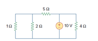
Figure 2.14
For Practice Prob. 2.4.
Expert Solution & Answer
Want to see the full answer?
Check out a sample textbook solution
Students have asked these similar questions
b) The circuit in Figure Q2(b) is referred.
i.
Show the supernode in the circuit. Explain the reason for your answer.
ii.
By using nodal analysis with supernode, solve for the node voltages at each
assigned nodes in the circuit.
2 A
12 V
Figure Q2(b)
Q2 (B)
Note: If Multisim not available then then do it on paper.
Verify Ohm’s Law using resistor of 1.5k Ohms on NI Multisim if the supplied voltages are:2V, 7V ,10V and 15V.Also plot the VI graph
Q2. Build the following full subtractor circuit by modifying the full adder circuit and simulate its results
D
O Cad
Chapter 2 Solutions
Fundamentals of Electric Circuits
Ch. 2.2 - The essential component of a toaster is an...Ch. 2.2 - For the circuit shown in Fig. 2.9, calculate the...Ch. 2.2 - A resistor absorbs an instantaneous power of 30...Ch. 2.3 - How many branches and nodes does the circuit in...Ch. 2.4 - Find v1 and v2 in the circuit of Fig. 2.22. Figure...Ch. 2.4 - Find vx and vo in the circuit of Fig. 2.24. Figure...Ch. 2.4 - Find vo and io in the circuit of Fig. 2.26. Figure...Ch. 2.4 - Find the current and voltages in the circuit shown...Ch. 2.6 - By combining the resistors in Fig.2.36, find Req....Ch. 2.6 - Find Rab for the circuit in Fig.2.39. Figure 2.39...
Ch. 2.6 - Calculate Geq in the circuit of Fig.2.41. Figure...Ch. 2.6 - Find v1 and v2 in the circuit shown in Fig. 2.43....Ch. 2.7 - Transform the wye network in Fig. 2.51 to a delta...Ch. 2.7 - For the bridge network in Fig. 2.54, find Rab and...Ch. 2.8 - Refer to Fig. 2.55 and assume there are six light...Ch. 2.8 - Following the ammeter setup of Fig. 2.61. design...Ch. 2 - The reciprocal of resistance is: (a) voltage (b)...Ch. 2 - Prob. 2RQCh. 2 - Prob. 3RQCh. 2 - The maximum current that a 2W, 80 k resistor can...Ch. 2 - Prob. 5RQCh. 2 - The current I in the circuit of Fig. 2.63 is: (a)...Ch. 2 - The current I0 of Fig. 2.64 is: (a) 4 A (b) 2 A...Ch. 2 - In the circuit in Fig. 2.65, V is: (a) 30 V (b) 14...Ch. 2 - Which of the circuit in Fig. 2.66 will give you...Ch. 2 - In the circuit of Fig. 2.67, a decrease in R3...Ch. 2 - Design a problem, complete with a solution, to...Ch. 2 - Find the hot resistance of a light bulb rated 60...Ch. 2 - A bar of silicon is 4 cm long with a circular...Ch. 2 - (a) Calculate current i in Fig. 2.68 when the...Ch. 2 - For the network graph in Fig. 2.69. find the...Ch. 2 - In the network graph shown in Fig. 2.70, determine...Ch. 2 - Determine the number of branches and nodes in the...Ch. 2 - Design a problem, complete with a solution, to...Ch. 2 - Find i1, i2, and i3 in Fig. 2.73. Figure 2.73 For...Ch. 2 - Determine i1 and i2 in the circuit of Fig. 2.74....Ch. 2 - In the circuit of Fig. 2.75, calculate V1 and V2....Ch. 2 - In the circuit in Fig. 2.76, obtain v1, v2, and...Ch. 2 - For the circuit in Fig. 2.77, use KCL to find the...Ch. 2 - Given the circuit in Fig. 2.78, use KVL to find...Ch. 2 - Calculate v and ix in the circuit of Fig. 2.79....Ch. 2 - Determine Vo in the circuit in Fig. 2.80. Figure...Ch. 2 - Obtain v1 through v3 in the circuit of Fig. 2.81....Ch. 2 - Find I and V in the circuit of Fig. 2.82. Figure...Ch. 2 - From the circuit in Fig. 2.83, find I, the power...Ch. 2 - Determine io in the circuit of Fig. 2.84. Figure...Ch. 2 - Find Vx in the circuit of Fig. 2.85. Figure 2.85...Ch. 2 - Find Vo in the circuit in Fig. 2.86 and the power...Ch. 2 - In the circuit shown in Fig. 2.87, determine Vx...Ch. 2 - For the circuit in Fig. 2.88, find Vo/Vs in terms...Ch. 2 - For the network in Fig. 2.89, find the current,...Ch. 2 - For the circuit in Fig. 2.90, io = 3 A. Calculate...Ch. 2 - Calculate Io in the circuit of Fig. 2.91. Figure...Ch. 2 - Design a problem, using Fig. 2.92, to help other...Ch. 2 - All resistors (R) in Fig. 2.93 are 10 each. Find...Ch. 2 - For the circuit in Fig. 2.95, determine i1 to i5....Ch. 2 - Find i1 through i4 in the circuit in Fig. 2.96....Ch. 2 - Obtain v and i in the circuit of Fig. 2.97. Figure...Ch. 2 - Using series/parallel resistance combination, find...Ch. 2 - Calculate Vo and Io in the circuit of Fig. 2.99....Ch. 2 - Find i and Vo in the circuit of Fig. 2.100. Figure...Ch. 2 - Given the circuit in Fig. 2.101 and that the...Ch. 2 - Find Req and io in the circuit of Fig. 2.102....Ch. 2 - Evaluate Req looking into each set of terminals...Ch. 2 - For the ladder network in Fig. 2.104, find I and...Ch. 2 - If Req = 50 in the circuit of Fig. 2.105, find R....Ch. 2 - Reduce each of the circuits in Fig. 2.106 to a...Ch. 2 - Calculate the equivalent resistance Rab at...Ch. 2 - For the circuits in Fig. 2.108, obtain the...Ch. 2 - Find the equivalent resistance at terminals a-b of...Ch. 2 - Find I in the circuit of Fig. 2.110. Figure 2.110Ch. 2 - Find the equivalent resistance Rab in the circuit...Ch. 2 - Convert the circuits in Fig. 2.112 from Y to ....Ch. 2 - Transform the circuits in Fig. 2.113 from to Y....Ch. 2 - Design a problem to help other students better...Ch. 2 - Obtain the equivalent resistance at the terminals...Ch. 2 - For the circuit shown in Fig. 2.116, find the...Ch. 2 - Obtain the equivalent resistance Rab in each of...Ch. 2 - Consider the circuit in Fig. 2.118. Find the...Ch. 2 - Calculate I0 in the circuit of Fig. 2.119. Figure...Ch. 2 - Determine V in the circuit of Fig. 2.120. Figure...Ch. 2 - Find Req and I in the circuit of Fig. 2.121....Ch. 2 - The 150 W tight bulb in Fig. 2.122 is rated at 110...Ch. 2 - If the three bulbs of Prob. 2.59 are connected in...Ch. 2 - As a design engineer, you are asked to design a...Ch. 2 - Prob. 62PCh. 2 - If an ammeter with an internal resistance of 100 ...Ch. 2 - The potentiometer (adjustable resistor) Rx in Fig....Ch. 2 - Design a circuit that uses a dArsonval meter (with...Ch. 2 - A 20-k/V voltmeter reads 10 V full scale. (a) What...Ch. 2 - (a) Obtain the voltage Vo in the circuit of Fig....Ch. 2 - (a) Find the current I in the circuit of Fig....Ch. 2 - A voltmeter used to measure Vo in the circuit in...Ch. 2 - (a) Consider the Wheatstone bridge shown in Fig....Ch. 2 - Figure 2.131 represents a model of a solar...Ch. 2 - Find Vo in the two-way power divider circuit in...Ch. 2 - An ammeter model consists of an ideal ammeter in...Ch. 2 - The circuit in Fig. 2.134 is to control the speed...Ch. 2 - Find Rab in the four-way power divider circuit in...Ch. 2 - Repeat Prob. 2.75 for the eight-way divider shown...Ch. 2 - Suppose your circuit laboratory has the following...Ch. 2 - In the circuit in Fig. 2.137, the wiper divides...Ch. 2 - Prob. 79CPCh. 2 - A loudspeaker is connected to an amplifier as...Ch. 2 - For a specific application, the circuit shown in...Ch. 2 - The pin diagram of a resistance array is shown in...Ch. 2 - Two delicate devices are rated as shown in Fig....
Knowledge Booster


Learn more about
Need a deep-dive on the concept behind this application? Look no further. Learn more about this topic, electrical-engineering and related others by exploring similar questions and additional content below.Similar questions
- Electrical Engineering SOLVE BOTHB AND C PARTS PLS. UPVOTE GUARANTEED. b Calculate below resistance values and re-draw below circuit by showing numeric resistance values. R1 = TO T=44 R2 = 4T Q solve both b and c parts pls R3 = 8T Q R4 = 16T Q Ry = 20T Q V; O R1 R2 V. R4 Express vo in terms of v, and calculate the gain of the circuit A =arrow_forwardMy Courses This course e. ТА EHide blo For the below circuit, perform a Delta==>Wye transformation and find R1 , R2 and R3 in Ohms. To assist you, the figure below has both the Y-connected resistors and the A-connected resistors. of 100 N 125 N 25 N 40 V 100 N 125 N 40 N 37.5 N 25 N Select one: a. R1=40 , R2=10 and R3=60 b. R1=60 , R2=D40 and R3=10 C. R1=10, R2=12.5 and R3=50 d. R1=50 , R2=12.5 and R3=10 Activate Windows If Yo = 4 V in the network shown, find VS.arrow_forwardAn independent voltage source is characterized by a terminal voltage which Select one: a. is completely independent of the current through it. on b. is completely independent of the power dissipated by it. c. is completely dependent on the current through it. d. None of the abovearrow_forward
- Tutorial Q1: Consider the circuit in Figure below; Find the equivalent resistance at terminals: (a) a-b, (b) c-d. 50 2 150 2 60 2 ww 100 2 100 2 b. ww 150 2 wwarrow_forwardEX Find is, in the circuit below 15ma 2.7arrow_forward3- A junction where two (or) more than two network elements meet is known as a node 4- The algebraic sum of voltages around any closed path in a network is equal to one 5- The basic laws for analyzing an electric circuit are Newtons laws 6- Relation between currents according to KCL for a node with two input current (Ii & I2)and two outputs (I3 & I4) is I1-12+I3+14=0 7- A 3-ohm and 6-ohm resistor are connected in parallel, and a 10-ohm resistor is in series with the combination. When 36 volts is applied to the three resistors, the total current in the circuit is 2 amps. 8- KCL and KVL is limited to write two equations for a particular circuit. 9- When assigning branch currents, you need not be concerned with the direction you choose. 10- For the circuit shown below (Fig.1) the value of resistance is 17.5 ohms 5 ohm 2 A 70 v 7 ohm R ? Fig.1arrow_forward
- = 200 N are connected such tha Four resistors, R1 = 100 N, R2 = 250 N, R3 = 350 N and R4 the parallel combination of R, and R2 is connected in series with the parallel combination c R3 and R4. The series-parallel combination is then connected across a 24 V DC power suppl A. Draw the schematic diagram and label the circuit elements. B. Calculate the equivalent resistance of the circuit. (Ans. Req C. Find the total current of the circuit, the voltage across each resistor and the current throug each resistor. = 198. 7013 Q)arrow_forwardElectrical Engineering For the final problem, consider the following circuit diagram: 12 Q 30 V Vx 60 Q 2"Vx B 6) For this circuit, please find and draw: a. The Thevenin equivalent circuit between A and B, using external excitation to find R. b. The Norton cquivalent circuit berween A and B. c. Review section 3-8 from the text. What value load resistor connected between A and B would yield maximum power transfer? How much power woukd this be?arrow_forwarda) What is the Norton equivalent circuit with respect to terminals a and b? What does this look like drawn? b) What is the Thevenin equivalent circuit with respect to terminals a and b? What does this look like drawn? c) What value of Ro would make Vo = 10 V? d) What value of Ro would result in the maximum power transfer to the Ro resistor? e) How much power would be transferred to a resistor with the value from d)?arrow_forward
- Refer to the figure. Given 2RRL² R2 = 3R2 – R_° a) Design the power supply cireuit so that vị = 3v,when R1 = 600 2. b) Assume input voltage is 180 V. Which resistor in the circuit dissipates the most power? What is the power? c) Which resistor dissipates the least power? What is the power? R: ww- R R ww + Vi R Vo RL b d wwarrow_forwardState maximum power transfer theorem and write where it is applied. Find the value of maximum power drawn by the resistor R in Figure 2arrow_forwarda) The ratio ,-V½ b) If Vs=16V, determine the Thevenin equivalent circuit at terminals a-b. c) What must be the value of a load resistor to be connected at a-b for maximum power transferred to it? What is the value of this maximum power? + V1 V3 Vs (+ a V2 V4 100arrow_forward
arrow_back_ios
SEE MORE QUESTIONS
arrow_forward_ios
Recommended textbooks for you
 Introductory Circuit Analysis (13th Edition)Electrical EngineeringISBN:9780133923605Author:Robert L. BoylestadPublisher:PEARSON
 Delmar's Standard Textbook Of ElectricityElectrical EngineeringISBN:9781337900348Author:Stephen L. HermanPublisher:Cengage Learning
 Programmable Logic ControllersElectrical EngineeringISBN:9780073373843Author:Frank D. PetruzellaPublisher:McGraw-Hill Education
 Fundamentals of Electric CircuitsElectrical EngineeringISBN:9780078028229Author:Charles K Alexander, Matthew SadikuPublisher:McGraw-Hill Education
 Electric Circuits. (11th Edition)Electrical EngineeringISBN:9780134746968Author:James W. Nilsson, Susan RiedelPublisher:PEARSON
 Engineering ElectromagneticsElectrical EngineeringISBN:9780078028151Author:Hayt, William H. (william Hart), Jr, BUCK, John A.Publisher:Mcgraw-hill Education,
Introductory Circuit Analysis (13th Edition)
Electrical Engineering
ISBN:9780133923605
Author:Robert L. Boylestad
Publisher:PEARSON
Delmar's Standard Textbook Of Electricity
Electrical Engineering
ISBN:9781337900348
Author:Stephen L. Herman
Publisher:Cengage Learning
Programmable Logic Controllers
Electrical Engineering
ISBN:9780073373843
Author:Frank D. Petruzella
Publisher:McGraw-Hill Education
Fundamentals of Electric Circuits
Electrical Engineering
ISBN:9780078028229
Author:Charles K Alexander, Matthew Sadiku
Publisher:McGraw-Hill Education
Electric Circuits. (11th Edition)
Electrical Engineering
ISBN:9780134746968
Author:James W. Nilsson, Susan Riedel
Publisher:PEARSON
Engineering Electromagnetics
Electrical Engineering
ISBN:9780078028151
Author:Hayt, William H. (william Hart), Jr, BUCK, John A.
Publisher:Mcgraw-hill Education,
Thevenin's Theorem; Author: Neso Academy;https://www.youtube.com/watch?v=veAFVTIpKyM;License: Standard YouTube License, CC-BY