
Fundamentals of Electric Circuits
6th Edition
ISBN: 9780078028229
Author: Charles K Alexander, Matthew Sadiku
Publisher: McGraw-Hill Education
expand_more
expand_more
format_list_bulleted
Concept explainers
Videos
Textbook Question
Chapter 2, Problem 44P
For the circuits in Fig. 2.108, obtain the equivalent resistance at terminals a-b.
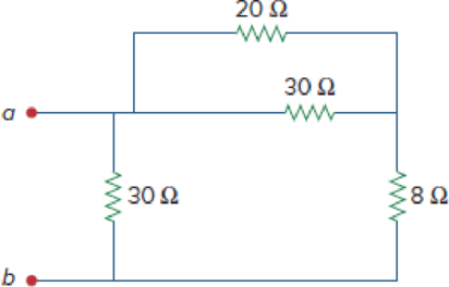
Figure 2.108
Expert Solution & Answer
Want to see the full answer?
Check out a sample textbook solution
Students have asked these similar questions
1.) Which of the following statement is not correct? -voltage source is an active element -current source is a passive element -resistance is a passive element -conductance is a passive element
2.) A battery produces a current of 0.6 A when the external resistance is 2 ? and 0.2 A when the external resistance is 12 ?. Find the emf of the battery -3 V -6 V -9 V -12 V
Calculate the ratio iC2/iC1 for (vBE2 − vBE1) = 0.2 V, 0.3 V and 0.4 V.
2- Give a definition of ohm's law for the three relationships between V,
I and R. Use the terin "proportional" and "inverse proportional ", and
also state the conditions for each individual relationship.
Chapter 2 Solutions
Fundamentals of Electric Circuits
Ch. 2.2 - The essential component of a toaster is an...Ch. 2.2 - For the circuit shown in Fig. 2.9, calculate the...Ch. 2.2 - A resistor absorbs an instantaneous power of 30...Ch. 2.3 - How many branches and nodes does the circuit in...Ch. 2.4 - Find v1 and v2 in the circuit of Fig. 2.22. Figure...Ch. 2.4 - Find vx and vo in the circuit of Fig. 2.24. Figure...Ch. 2.4 - Find vo and io in the circuit of Fig. 2.26. Figure...Ch. 2.4 - Find the current and voltages in the circuit shown...Ch. 2.6 - By combining the resistors in Fig.2.36, find Req....Ch. 2.6 - Find Rab for the circuit in Fig.2.39. Figure 2.39...
Ch. 2.6 - Calculate Geq in the circuit of Fig.2.41. Figure...Ch. 2.6 - Find v1 and v2 in the circuit shown in Fig. 2.43....Ch. 2.7 - Transform the wye network in Fig. 2.51 to a delta...Ch. 2.7 - For the bridge network in Fig. 2.54, find Rab and...Ch. 2.8 - Refer to Fig. 2.55 and assume there are six light...Ch. 2.8 - Following the ammeter setup of Fig. 2.61. design...Ch. 2 - The reciprocal of resistance is: (a) voltage (b)...Ch. 2 - Prob. 2RQCh. 2 - Prob. 3RQCh. 2 - The maximum current that a 2W, 80 k resistor can...Ch. 2 - Prob. 5RQCh. 2 - The current I in the circuit of Fig. 2.63 is: (a)...Ch. 2 - The current I0 of Fig. 2.64 is: (a) 4 A (b) 2 A...Ch. 2 - In the circuit in Fig. 2.65, V is: (a) 30 V (b) 14...Ch. 2 - Which of the circuit in Fig. 2.66 will give you...Ch. 2 - In the circuit of Fig. 2.67, a decrease in R3...Ch. 2 - Design a problem, complete with a solution, to...Ch. 2 - Find the hot resistance of a light bulb rated 60...Ch. 2 - A bar of silicon is 4 cm long with a circular...Ch. 2 - (a) Calculate current i in Fig. 2.68 when the...Ch. 2 - For the network graph in Fig. 2.69. find the...Ch. 2 - In the network graph shown in Fig. 2.70, determine...Ch. 2 - Determine the number of branches and nodes in the...Ch. 2 - Design a problem, complete with a solution, to...Ch. 2 - Find i1, i2, and i3 in Fig. 2.73. Figure 2.73 For...Ch. 2 - Determine i1 and i2 in the circuit of Fig. 2.74....Ch. 2 - In the circuit of Fig. 2.75, calculate V1 and V2....Ch. 2 - In the circuit in Fig. 2.76, obtain v1, v2, and...Ch. 2 - For the circuit in Fig. 2.77, use KCL to find the...Ch. 2 - Given the circuit in Fig. 2.78, use KVL to find...Ch. 2 - Calculate v and ix in the circuit of Fig. 2.79....Ch. 2 - Determine Vo in the circuit in Fig. 2.80. Figure...Ch. 2 - Obtain v1 through v3 in the circuit of Fig. 2.81....Ch. 2 - Find I and V in the circuit of Fig. 2.82. Figure...Ch. 2 - From the circuit in Fig. 2.83, find I, the power...Ch. 2 - Determine io in the circuit of Fig. 2.84. Figure...Ch. 2 - Find Vx in the circuit of Fig. 2.85. Figure 2.85...Ch. 2 - Find Vo in the circuit in Fig. 2.86 and the power...Ch. 2 - In the circuit shown in Fig. 2.87, determine Vx...Ch. 2 - For the circuit in Fig. 2.88, find Vo/Vs in terms...Ch. 2 - For the network in Fig. 2.89, find the current,...Ch. 2 - For the circuit in Fig. 2.90, io = 3 A. Calculate...Ch. 2 - Calculate Io in the circuit of Fig. 2.91. Figure...Ch. 2 - Design a problem, using Fig. 2.92, to help other...Ch. 2 - All resistors (R) in Fig. 2.93 are 10 each. Find...Ch. 2 - For the circuit in Fig. 2.95, determine i1 to i5....Ch. 2 - Find i1 through i4 in the circuit in Fig. 2.96....Ch. 2 - Obtain v and i in the circuit of Fig. 2.97. Figure...Ch. 2 - Using series/parallel resistance combination, find...Ch. 2 - Calculate Vo and Io in the circuit of Fig. 2.99....Ch. 2 - Find i and Vo in the circuit of Fig. 2.100. Figure...Ch. 2 - Given the circuit in Fig. 2.101 and that the...Ch. 2 - Find Req and io in the circuit of Fig. 2.102....Ch. 2 - Evaluate Req looking into each set of terminals...Ch. 2 - For the ladder network in Fig. 2.104, find I and...Ch. 2 - If Req = 50 in the circuit of Fig. 2.105, find R....Ch. 2 - Reduce each of the circuits in Fig. 2.106 to a...Ch. 2 - Calculate the equivalent resistance Rab at...Ch. 2 - For the circuits in Fig. 2.108, obtain the...Ch. 2 - Find the equivalent resistance at terminals a-b of...Ch. 2 - Find I in the circuit of Fig. 2.110. Figure 2.110Ch. 2 - Find the equivalent resistance Rab in the circuit...Ch. 2 - Convert the circuits in Fig. 2.112 from Y to ....Ch. 2 - Transform the circuits in Fig. 2.113 from to Y....Ch. 2 - Design a problem to help other students better...Ch. 2 - Obtain the equivalent resistance at the terminals...Ch. 2 - For the circuit shown in Fig. 2.116, find the...Ch. 2 - Obtain the equivalent resistance Rab in each of...Ch. 2 - Consider the circuit in Fig. 2.118. Find the...Ch. 2 - Calculate I0 in the circuit of Fig. 2.119. Figure...Ch. 2 - Determine V in the circuit of Fig. 2.120. Figure...Ch. 2 - Find Req and I in the circuit of Fig. 2.121....Ch. 2 - The 150 W tight bulb in Fig. 2.122 is rated at 110...Ch. 2 - If the three bulbs of Prob. 2.59 are connected in...Ch. 2 - As a design engineer, you are asked to design a...Ch. 2 - Prob. 62PCh. 2 - If an ammeter with an internal resistance of 100 ...Ch. 2 - The potentiometer (adjustable resistor) Rx in Fig....Ch. 2 - Design a circuit that uses a dArsonval meter (with...Ch. 2 - A 20-k/V voltmeter reads 10 V full scale. (a) What...Ch. 2 - (a) Obtain the voltage Vo in the circuit of Fig....Ch. 2 - (a) Find the current I in the circuit of Fig....Ch. 2 - A voltmeter used to measure Vo in the circuit in...Ch. 2 - (a) Consider the Wheatstone bridge shown in Fig....Ch. 2 - Figure 2.131 represents a model of a solar...Ch. 2 - Find Vo in the two-way power divider circuit in...Ch. 2 - An ammeter model consists of an ideal ammeter in...Ch. 2 - The circuit in Fig. 2.134 is to control the speed...Ch. 2 - Find Rab in the four-way power divider circuit in...Ch. 2 - Repeat Prob. 2.75 for the eight-way divider shown...Ch. 2 - Suppose your circuit laboratory has the following...Ch. 2 - In the circuit in Fig. 2.137, the wiper divides...Ch. 2 - Prob. 79CPCh. 2 - A loudspeaker is connected to an amplifier as...Ch. 2 - For a specific application, the circuit shown in...Ch. 2 - The pin diagram of a resistance array is shown in...Ch. 2 - Two delicate devices are rated as shown in Fig....
Knowledge Booster


Learn more about
Need a deep-dive on the concept behind this application? Look no further. Learn more about this topic, electrical-engineering and related others by exploring similar questions and additional content below.Similar questions
- B 12 V (+ 32 kn I, A 1 kM 2 kN 1 kN 2 mA Darrow_forwardA 230-V, 1 000-c/s voltage is applied to a resistor in series with C capacıtance 0 06 µF, the reading is 100 V. Find the current when the voltmeter is disconnected. 86 0 05 µF. When C is shunted by a voltmeter of [0 0527 A.]arrow_forwardA practical battery has an internal resistance of 0.2 ohm. If this practical battery provides a power of 25 watts to a load with resistance 10 ohms, find 1. the terminal voltage across the battery if it were to be disconnected from the circuitarrow_forward
- a. All resistors in the given figure are 5ohms each. Find Req. -ww Req b..(a) Calculate current i in the given figure when the switch is in position 1. (b) Find the current when the switch is in position 2 100 £2 ww 15 V 150 £2arrow_forwardPlease show complete solution. Please check the circuit/ figure. Find the following: V1 V2 V3 V6 R45 R2345 Itotal I2 I1 Vtotalarrow_forward3.1 Find the equivalent resistance Rab for each of the circuits in the following figure. a b 5052 9052 {30012 802 $10052 $7052arrow_forward
- INSTRUCTIONS: Solve the following problems. Show and COMPLETE solutions. Draw all CIRCUIT DIAGRAMS or the equivalent circuit (dummy circuit) as the case may be. Write your solutions on sheet/s of short bond paper. A battery is to consist of 20 identical cells. The emf of each cell is 1.5 V and the internal resistance is 0.20 ohm. This battery will be used to supply power to a 10 ohm lamp. Determine the current on the lamp if:1. The 20 cells are connected in series 2. The 20 cells are connected in parallel 3. The 20 cells are arranged 5 cells in series in 4 parallel rows.arrow_forward1. Two identical batteries are available. If the batteries are connected in series and a voltmeter is used to measure its terminal voltage, the voltmeter reads 18 V. If the batteries are connected in series to supply power to load R, R receives 6 A. If the batteries are connected in parallel to supply power to the same load R, R receives 10/3 A Find the Emf (E) and internal resistance (r) of each battery and the value of R.arrow_forward4. A battery has an internal resistance of 0.50 and EMF of 2V. When connected in series to a load resistance, the terminal voltage falls to 1.75V. What current is flowing in the circuit, and what is the value of the load resistance? (Show your solution)arrow_forward
- Consider a PV Module with 8 PV cells with the Size of each 10cm x 5cm are connected in series. Calculate the following for the above Module. a. The output voltage is 4V, the output power is 6W b. The output voltage is 4V, the output power is 8W c. The output voltage is 8V, the output power is 1.5W d. The output voltage is 8V, the output power is 6Warrow_forward23. Resistors R1, R2, and R3 have resistances of 15.0 2, 9.0 2, and 8.0 Q Orespectively. Rı and R2 are connected in series, and their combination is in parallel with R3 to form a load across a 6.0-V battery. a. Draw the circuit diagram.arrow_forwardFor the circuit shown below, find the value of k so that the equivalent resistance is a minimum. ka n a ka aarrow_forward
arrow_back_ios
SEE MORE QUESTIONS
arrow_forward_ios
Recommended textbooks for you
 Introductory Circuit Analysis (13th Edition)Electrical EngineeringISBN:9780133923605Author:Robert L. BoylestadPublisher:PEARSON
 Delmar's Standard Textbook Of ElectricityElectrical EngineeringISBN:9781337900348Author:Stephen L. HermanPublisher:Cengage Learning
 Programmable Logic ControllersElectrical EngineeringISBN:9780073373843Author:Frank D. PetruzellaPublisher:McGraw-Hill Education
 Fundamentals of Electric CircuitsElectrical EngineeringISBN:9780078028229Author:Charles K Alexander, Matthew SadikuPublisher:McGraw-Hill Education
 Electric Circuits. (11th Edition)Electrical EngineeringISBN:9780134746968Author:James W. Nilsson, Susan RiedelPublisher:PEARSON
 Engineering ElectromagneticsElectrical EngineeringISBN:9780078028151Author:Hayt, William H. (william Hart), Jr, BUCK, John A.Publisher:Mcgraw-hill Education,
Introductory Circuit Analysis (13th Edition)
Electrical Engineering
ISBN:9780133923605
Author:Robert L. Boylestad
Publisher:PEARSON
Delmar's Standard Textbook Of Electricity
Electrical Engineering
ISBN:9781337900348
Author:Stephen L. Herman
Publisher:Cengage Learning
Programmable Logic Controllers
Electrical Engineering
ISBN:9780073373843
Author:Frank D. Petruzella
Publisher:McGraw-Hill Education
Fundamentals of Electric Circuits
Electrical Engineering
ISBN:9780078028229
Author:Charles K Alexander, Matthew Sadiku
Publisher:McGraw-Hill Education
Electric Circuits. (11th Edition)
Electrical Engineering
ISBN:9780134746968
Author:James W. Nilsson, Susan Riedel
Publisher:PEARSON
Engineering Electromagnetics
Electrical Engineering
ISBN:9780078028151
Author:Hayt, William H. (william Hart), Jr, BUCK, John A.
Publisher:Mcgraw-hill Education,
Current Divider Rule; Author: Neso Academy;https://www.youtube.com/watch?v=hRU1mKWUehY;License: Standard YouTube License, CC-BY