
Applied Statics and Strength of Materials (6th Edition)
6th Edition
ISBN: 9780133840544
Author: George F. Limbrunner, Craig D'Allaird, Leonard Spiegel
Publisher: PEARSON
expand_more
expand_more
format_list_bulleted
Concept explainers
Videos
Textbook Question
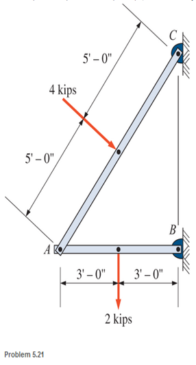
Chapter 5, Problem 5.21P
A simple frame is pin connected at points A, B, and C and is subjected to loads as shown. Compute the pin reactions at A, B, and C. Neglect the weights of the members.
Expert Solution & Answer
Want to see the full answer?
Check out a sample textbook solution
Students have asked these similar questions
2- Calculate the force acting on the GH rod in the truss system shown in the figure by using the section method.
Compute for the external reactions for all members of the frame shown. Please solve the following:
Vertical Reaction at A
Horizontal Reaction at A
Vertical Reaction at E
Vertical Reaction at D
Vertical Reaction at B
Vertical Reaction at C
Horizontal Reaction at C
Horizontal Reaction at B
Horizontal Reaction at D
Compute for the external reactions for all members of the frame shown. Please solve the following:
Vertical Reaction at C = 624 (WRONG)
Horizontal Reaction at C = 400 (WRONG)
Horizontal Reaction at B = 400 (WRONG)
Horizontal Reaction at D = 400 (WRONG)
Chapter 5 Solutions
Applied Statics and Strength of Materials (6th Edition)
Ch. 5 - through 5.7 Calculate the forces in all members of...Ch. 5 - Calculate the forces in all members of the trusses...Ch. 5 - Calculate the forces in all members of the trusses...Ch. 5 - Calculate the forces in all members of the trusses...Ch. 5 - Calculate the forces in all members of the trusses...Ch. 5 - Calculate the forces in all members of the trusses...Ch. 5 - Calculate the forces in all members of the trusses...Ch. 5 - Determine the forces in members CD, DH, and HI for...Ch. 5 - Determine the forces in members BC, BE, and FE for...Ch. 5 - Determine the forces in members BC, CH, and CG in...
Ch. 5 - For the Howe roof truss shown, determine the...Ch. 5 - Determine the forces in members DE, CE, and BC in...Ch. 5 - Calculate the forces in members BC, BG, and FG for...Ch. 5 - Determine the forces in members CD, BD, BE, and CB...Ch. 5 - A pin-connected A-frame supports a load, as shown....Ch. 5 - Determine the pin reactions at pins A, B, and C in...Ch. 5 - Calculate the pin reactions at each of the pins in...Ch. 5 - A bracket is pin connected at points A, B, and D...Ch. 5 - A pin-connected frame is loaded, as shown....Ch. 5 - The cylinder shown has a mass of 500 kg. Determine...Ch. 5 - A simple frame is pin connected at points A, B,...Ch. 5 - Using the method of sections, determine the forces...Ch. 5 - Using the method of sections, determine the forces...Ch. 5 - through 5.31 Calculate the forces in all members...Ch. 5 - Calculate the forces in all members of the trusses...Ch. 5 - Calculate the forces in all members of the trusses...Ch. 5 - Calculate the forces in all members of the trusses...Ch. 5 - Calculate the forces in all members of the trusses...Ch. 5 - Calculate the forces in all members of the trusses...Ch. 5 - Calculate the forces in all members of the trusses...Ch. 5 - Calculate the forces in all members of the trusses...Ch. 5 - For Problems 5.32 through 5.38, calculate the...Ch. 5 - For Problem 5.32 through 5.38, Calculate the...Ch. 5 - For Problems 5.32 through 5.38, calculate the...Ch. 5 - For Problems 5.32 through 5.38, calculate the...Ch. 5 - For Problem 5.32 through 5.38 , Calculate the...Ch. 5 - For Problems 5.32 through 5.38, calculate the...Ch. 5 - For Problems 5.32 through 5.38, calculate the...Ch. 5 - A pin-connected crane framework is loaded and...Ch. 5 - Calculate the pin reactions at pins A, B, and D in...Ch. 5 - Determine the pin reactions at pins A, B, and C in...Ch. 5 - The wall bracket shown is pin-connected at points...Ch. 5 - Calculate the pin reactions at each of the pins in...Ch. 5 - The A-frame shown is pin-connected at A,B,C, and...Ch. 5 - The tongs shown are used to grip an object. For an...Ch. 5 - A toggle joint is a mechanism by which a...Ch. 5 - In the toggle joint of Problem 5.46 , assume that...Ch. 5 -
Knowledge Booster


Learn more about
Need a deep-dive on the concept behind this application? Look no further. Learn more about this topic, mechanical-engineering and related others by exploring similar questions and additional content below.Similar questions
- Compute the magnitude of the pin reaction at B. Neglect the weights of the structural members.arrow_forwardCompute the magnitudes of the reactions at pin A and the roller at D. Neglect the weight of the body.arrow_forwardThe figure shows a three-pin arch. Determine the horizontal component of the pin reaction at A caused by the applied force P.arrow_forward
- Find the magnitude of the pin reaction at B caused by the weight W=80lb. Neglect the weights of the members.arrow_forwardFind the force P required to (a) push; and (b) pull the 80-lb homogeneous roller over the 3-in. curb.arrow_forwardThe rigid frame loaded as shown has pins at support A and D. The connections at B and C are rigid. The frame is loaded with a uniform load (3k/ft) acting on member BC, it has a triangular load (6k/ft) acting on member CD, it has an applied couple of 30 ft-K at point B and a concentrated load of 12K at point C. Determine the reactions and draw the moment diagram. Use Ax as the redundant force reaction. EI is constant.arrow_forward
- A simple beam is subjected to vertical concentrated and uniformly distributed loads shown below. The beam is pin supported at A and roller supported at B. Calculate the reactions at each support. Neglect the weight of the beamarrow_forwardThe image depicts the components of a floor jack. If the hydraulic cylinder AB is intended to withstand a maximum compressive force of 37 kN, find the load L (in kN) and force (in kN) in link EF under this circumstance. Additionally, compute the pin reaction (in kN) at C. The hydraulic cylinder AB, the link EF, and the platform DF all have the necessary FBDs. Additionally, create a combined FBD for the platform DF and the member BCD. Take note that if the figure CDFE is traced, it becomes a parallelogram. Additionally, members BCD and EF are connected to the jack's base via pins at C and E. Disregard the friction between members BCD and EF's contacting faces.arrow_forwardConsider the pin connected frame. Compute for the reactions at the supports and the reactions at the jointsarrow_forward
- Draw the free-body diagram for the following problem. The rod shown.arrow_forwardCalculate the support reactions at pin B and roller A that result from the applied loads shown. You must show a FBD drawn with a straight edge and all unknowns must be labeledand the same labels used in your calculations.arrow_forwardFigure 1: For the frame shown, determine the magnitude of the pin reaction at B. Neglect the weight of the frame. (2 decimal point, indicate the answer in kN. Ex: 3.87kN just encode 3.78)arrow_forward
arrow_back_ios
SEE MORE QUESTIONS
arrow_forward_ios
Recommended textbooks for you
 International Edition---engineering Mechanics: St...Mechanical EngineeringISBN:9781305501607Author:Andrew Pytel And Jaan KiusalaasPublisher:CENGAGE L
International Edition---engineering Mechanics: St...
Mechanical Engineering
ISBN:9781305501607
Author:Andrew Pytel And Jaan Kiusalaas
Publisher:CENGAGE L
Types Of loads - Engineering Mechanics | Abhishek Explained; Author: Prime Course;https://www.youtube.com/watch?v=4JVoL9wb5yM;License: Standard YouTube License, CC-BY