
Concept explainers
Videos
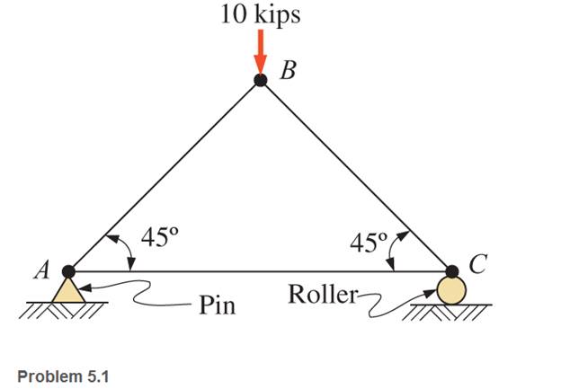
through 5.7 Calculate the forces in all members of the trusses shown, using the method of joints.
The forces in the member from method of joints.
Answer to Problem 5.1P
Explanation of Solution
Given:
Two reactions at the pin support is Ax and Ay.
At roller support one reaction is Cy.
Force on the member
Free body diagram of the truss.
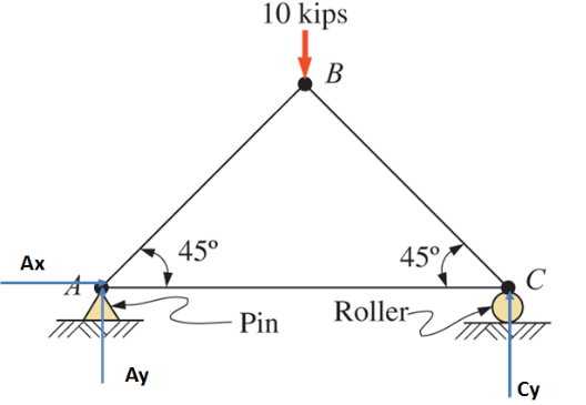
Taking moment about A
From equilibrium equations
Considering joint A
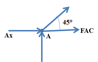
From the equilibrium equation
Considering joint C
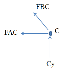
Conclusion:
Forces in the member
Want to see more full solutions like this?
Chapter 5 Solutions
Applied Statics and Strength of Materials (6th Edition)
Additional Engineering Textbook Solutions
Statics and Mechanics of Materials (5th Edition)
Applied Fluid Mechanics (7th Edition)
Engineering Mechanics: Statics
Mechanics of Materials
Engineering Mechanics: Statics & Dynamics (14th Edition)
Thinking Like an Engineer: An Active Learning Approach (4th Edition)


- For the next Trusses, compute the axial forces in the selected sections. Compare the result with the method of joints. (Check the image for the trusses)arrow_forward1) calculate the force in each member of the loaded truss illustrated and state weather each member is in tension or compression by using the method of Joints. Also calculate the reaction forces at D and E.arrow_forwardFor the truss shown below: 1. Calculate the force in all members (Using the method of joints). 2. Indicate if members AB, BE, and DE are compression or tension members. 3. Calculate the force in member BE (Using the method of sections). 4. Compare the results for part (1) and part (2) 4 m A 3 m 12 kN D B 3 m E 3 kN Carrow_forward
- Determine the member forces for all members in each truss shown using the method on joints. Remember to list each member force as either tension or compression.arrow_forwardQ: Find the force in members AC and BC of the Truss shown below?arrow_forward1) Calculate the length of members AD, DC and BD. 2) Calculate the reaction forces at A and C. 3) Using joint method, calculate the forces in members AD and AB. Note: Assume that the truss has a fixed support at A and a roller support at C.arrow_forward
- Use the method of sections to compute for the force in members BD, CD, and CE of the cantilever truss described in the figure below.arrow_forwardThe Warren truss loaded as shown in the figure is supported by a roller at C and a hinge at G. By the method of sections, compute the force in the members BC, DF, and CE.arrow_forwardLooking at the figure assume the truss is pin supported on both ends. Calculate the axial forces in members: AB, BC, BD, and BE.arrow_forward
- Find the magnitude and nature of the forces in all the members of the given truss. Figure: 3aand 3barrow_forwardFor the truss shown below and using the method of joints, find the forces acting along segment AB, and ACarrow_forwardIn the Fink truss shown in below with symmetrical loadings, BC and EF are perpendicular to the inclined members at their mid points. Use the method of joints to determine the forces in each member. Hint : Solve first for the reaction at A and G.arrow_forward
 Elements Of ElectromagneticsMechanical EngineeringISBN:9780190698614Author:Sadiku, Matthew N. O.Publisher:Oxford University Press
 Mechanics of Materials (10th Edition)Mechanical EngineeringISBN:9780134319650Author:Russell C. HibbelerPublisher:PEARSON
 Thermodynamics: An Engineering ApproachMechanical EngineeringISBN:9781259822674Author:Yunus A. Cengel Dr., Michael A. BolesPublisher:McGraw-Hill Education
 Control Systems EngineeringMechanical EngineeringISBN:9781118170519Author:Norman S. NisePublisher:WILEY
 Mechanics of Materials (MindTap Course List)Mechanical EngineeringISBN:9781337093347Author:Barry J. Goodno, James M. GerePublisher:Cengage Learning
 Engineering Mechanics: StaticsMechanical EngineeringISBN:9781118807330Author:James L. Meriam, L. G. Kraige, J. N. BoltonPublisher:WILEY