
Applied Statics and Strength of Materials (6th Edition)
6th Edition
ISBN: 9780133840544
Author: George F. Limbrunner, Craig D'Allaird, Leonard Spiegel
Publisher: PEARSON
expand_more
expand_more
format_list_bulleted
Videos
Textbook Question
Chapter 3, Problem 3.35P
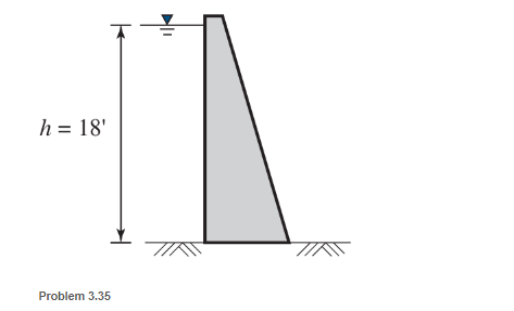
Fresh water is impounded behind a dam to a height h of 18 ft. as shown
a. Determine the maximum pressure behind the dam.
b. Determine the resultant force on a typical 1-ft-wide (18-ft-high) segment of the dam.
c. Locate the position of the resultant force with respect to the bottom of the dam.
Expert Solution & Answer
Want to see the full answer?
Check out a sample textbook solution
Students have asked these similar questions
Situation 9. The figure shows the water pressure acting on the sides of a dam that is 20-m long. Determine the resultant force
of the water pressure acting on the dam.
The face of a dam adjacent to the water has the shape of an isosceles trapezoid of altitude 20 m, upper base 50 m, and lower base 40 m. Find the total force exerted by the water on the dam when the water is 15 m deep.
2) The form is used to cast a concrete wall having a width of 5 m. determine the equivalent
resultant force the wet concrete exerts on the form AB if the pressure distribution due to the
concrete can be approximated as shown. Specify the location of the resultant force, measured
from point B.
p = (422) kPa-
8 kPa
B
4 m
Chapter 3 Solutions
Applied Statics and Strength of Materials (6th Edition)
Ch. 3 - through 3.3 Determine the magnitude, direction,...Ch. 3 - Determine the magnitude, direction, and sense of...Ch. 3 - Determine the magnitude, direction, and sense of...Ch. 3 - Solve Problem 3.1 through 3.3 using the method of...Ch. 3 - Solve Problem 3.1 through 3.3 using the method of...Ch. 3 - through 3.6 Solve Problem 3.1 through 3.3 using...Ch. 3 - The 150-lb force shown is the resultant of two...Ch. 3 - Find the resultant force P exerted on the tree.Ch. 3 - Find the resultant force R exerted on the pole.Ch. 3 - Calculate the resultant force on the screw eye....
Ch. 3 - Determine the resultant of the coplanar concurrent...Ch. 3 - Use the parallelogram law to find the following...Ch. 3 - Prob. 3.13PCh. 3 - Determine the resultant of the coplanar concurrent...Ch. 3 - The resultant of the concurrent force system shown...Ch. 3 - Three force of 900 lb, 1000 lb, and 600 lb are...Ch. 3 - The four forces shown hade parallel lines of...Ch. 3 - Three coplanar concurrent forces act as shown. a....Ch. 3 - Four coplanar concurrent forces act as shown a....Ch. 3 - Determine the resultant of the four forces of...Ch. 3 - For the concrete wall and footing shown: a....Ch. 3 - Calculate the moment of the 550-lb force about...Ch. 3 - In Problem 3.22 , calculate the moment about point...Ch. 3 - Compute the moment about point A for the linkage...Ch. 3 - Compute the moment of the force F about point A...Ch. 3 - Determine the magnitude of the resultant of the...Ch. 3 - Determine the magnitude of the resultant of the...Ch. 3 - Determine the magnitude of the resultant of the...Ch. 3 - Determine the magnitude of the resultant of the...Ch. 3 - Determine the resultant and its location for the...Ch. 3 - Compute the magnitude, sense, and location of the...Ch. 3 - Compute the magnitude, sense, and location of the...Ch. 3 - Compute the magnitude and location of the...Ch. 3 - Determine the magnitude and location of the...Ch. 3 - Fresh water is impounded behind a dam to a height...Ch. 3 - Determine the magnitude and location of the...Ch. 3 - Determine the magnitude and location of the...Ch. 3 - Compute the magnitude and direction of the...Ch. 3 - Compute the magnitude and direction of the...Ch. 3 - Compute the magnitude and direction of the...Ch. 3 - A body is subjected to the following three...Ch. 3 - Determine the magnitude, direction, and sense of...Ch. 3 - Determine the magnitude, direction, and sense of...Ch. 3 - Determine the resultant of the load system shown....Ch. 3 - For the concrete structure shown, determine the...Ch. 3 - For the following computer problems, any...Ch. 3 - For the following computer problems, any...Ch. 3 - For the following computer problems, any...Ch. 3 - 3.49 Determine the magnitude, direction, and sense...Ch. 3 - The resultant and one-component force of a...Ch. 3 - The resultant force of a concurrent force system...Ch. 3 - Determine the magnitudes of forces P1 and P2 such...Ch. 3 - The resultant force of a concurrent force system...Ch. 3 - A hockey puck is acted on simultaneously by two...Ch. 3 - Determine the resultant force for each of the...Ch. 3 - Determine the resultant force for each of the...Ch. 3 - The resultant of the three concurrent forces shown...Ch. 3 - The transmission tower shown is subjected to a...Ch. 3 - A gravity-type masonry dam, as shown, depends on...Ch. 3 - The transfomer (as shown) must be lifted...Ch. 3 - Refer to the diagram for Problem 3.60 /. Assume...Ch. 3 - The plastic barrel tent anchor of Problem 2.11...Ch. 3 - Calculate the moment of the forces shown with...Ch. 3 - Determine the magnitude and location of the...Ch. 3 - Determine the moment (about point A) of the appied...Ch. 3 - The lift force on the wing of an aircraft is...Ch. 3 - A beam is subjected to distributed loads as shown....Ch. 3 - For the concrete gravity wall shown, determine the...Ch. 3 - Fresh water is impounded to a height of 8 ft...Ch. 3 - Plank, 2 in. by 10 in. in cross section and 5 ft...Ch. 3 - a. Compute the moment (about point A) of the...Ch. 3 - Determine the resultant of the three forces acting...Ch. 3 - a. Calculate the moments about points A and B due...Ch. 3 - Determine the magnitude of F1 and F2 shown such...Ch. 3 - Calculate the magnitude, direction, and sense of...
Knowledge Booster


Learn more about
Need a deep-dive on the concept behind this application? Look no further. Learn more about this topic, mechanical-engineering and related others by exploring similar questions and additional content below.Similar questions
- The center of gravity of the 850-N man is at G. If the man pulls on the rope with a 388-N force, determine the horizontal distance b between the man's feet and G.arrow_forwardThe concrete dam shown in cross section holds back fresh water (=1000kg/m3). Determine the resultant force R of the water pressure acting on one meter length of the dam. Also, compute the coordinates of a point on the line of action of R.arrow_forwardDetermine the resultant force acting on the elbow of the thin-walled pipe when the pipe carries a uniform internal pressure p0.arrow_forward
- Determine the force F required to pull up the 3.54m stopper from the drain of a sink if the depth of water is 10 in. Use =0.036lb/in.3 for water and neglect the weight of the chain.arrow_forwardThe cylindrical water tank with R = 10 ft and H = 1.6 ft has thin steel walls of uniform thickness and weighs 18000 lb when empty. Determine the depth of the water h for which the center of gravity G of the tank plus water will be located at the surface of the water. For water, use =62.4lb/ft3.arrow_forward3. For the canal gate shown, sketch the pressure distributions applied to it. Sketch the resultant force on the gate? If h1 = 6.0 m and h2 = 4.0 m, sketch the pressure distribution to the gate. Also, what is the value of the resultant force on the gate and at what height above the bottom of the gate is it applied h₂arrow_forward
- Q6/ A tank wall has the shape shown in Fig. Determine the horizontal and vertical Water Tank wall components of the force of the water on a4 -ft length of the curved section AB. 18 ft 6 ftarrow_forward4. The figure on the right shows a gate for a dam enclosing a seawater (S.G. = 1.03) which is having a curved portion. When the water level rises to a certain height, the fluid forces acting on the gate open it which will through. Given that the gate is 0.7m wide and is designed so that the water level does not exceed to 2m, determine a. The components of the hydrostatic force acting the sea water to pass cause Tan tince 2m on the curved portion. b. The magnitude of the hydrostatic forces c. The required length, L of the straight portion of the gatearrow_forwardDetermine the resultant hydrostatic force the water exerts on a 1 ft width of the sloping upstream face of the gray dam. (Enter the magnitude in kips and direction in degrees below the horizontal.) 21 ft Dam 37 ft 41 ft magnitude kips direction ° below the horizontal Determine the location d in feet at which it acts along the back face of the dam. ftarrow_forward
- A force of 460 N is exerted on level AB as shown. The end B is connected to a piston which fits into a cylinder having a diameter of 60 mm. What force Fd acts on the larger piston, if the volume between C and D is filled with water?arrow_forwardIf the vertical wall is 20 feet wide. Calculate the force on the wall caused by the water pressure and locate its center of pressure. Also determine the moment exerted by the force at the base of the wall.arrow_forwardA dam consists of a vertical concrete wall 8 ft high. When the water in front of the wall is 6 ft deep, what is the maximum moment tending to overturn the dam? If the centers of gravity of the given plane surfaces are submerged 6 ftarrow_forward
arrow_back_ios
SEE MORE QUESTIONS
arrow_forward_ios
Recommended textbooks for you
 International Edition---engineering Mechanics: St...Mechanical EngineeringISBN:9781305501607Author:Andrew Pytel And Jaan KiusalaasPublisher:CENGAGE L
International Edition---engineering Mechanics: St...
Mechanical Engineering
ISBN:9781305501607
Author:Andrew Pytel And Jaan Kiusalaas
Publisher:CENGAGE L
How to balance a see saw using moments example problem; Author: Engineer4Free;https://www.youtube.com/watch?v=d7tX37j-iHU;License: Standard Youtube License