
Applied Statics and Strength of Materials (6th Edition)
6th Edition
ISBN: 9780133840544
Author: George F. Limbrunner, Craig D'Allaird, Leonard Spiegel
Publisher: PEARSON
expand_more
expand_more
format_list_bulleted
Concept explainers
Videos
Textbook Question
Chapter 3, Problem 3.17P
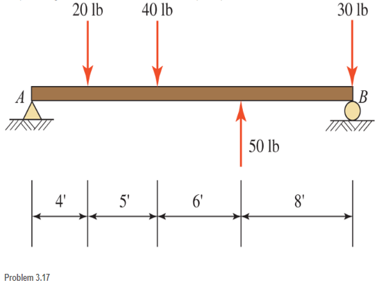
The four forces shown hade parallel lines of action. Member AB is perpendicular to the lines of action of these forces.
a. Determine the moment of each force with respect to point A
b. Compute the algebraic summation of the moments with respect to point A. Be sure to note the sense of the resultant moment.
Expert Solution & Answer

Learn your wayIncludes step-by-step video

schedule04:09
Students have asked these similar questions
the moment of the force F about the X axis is 960 N.m. If H is the midpoint, calculate in N.m the magnitude of the moment of the force F about the axis EH.
Using the figure for Question 4,a. Determine the x and y components of F1 and F2b. Slide F1 wherein its tail will touch the x-axis of point A then find the moment of F1 around point A. c. Slide F1 wherein its tail will touch the y-axis of point A then find the moment of F1 around point A.d. Determine the resultant force (magnitude and direction with respect to the +x axis) of F1, F2, C1.e. Determine the resultant moment (magnitude and rotation) of F1, F2, C1 around point A.
Force F, which has a magnitude of 10 kN, acts along a line passing through points D and D'. The grid units are in meters and counter-clockwise moments are positive. Determine the moment of the force about point B.
Chapter 3 Solutions
Applied Statics and Strength of Materials (6th Edition)
Ch. 3 - through 3.3 Determine the magnitude, direction,...Ch. 3 - Determine the magnitude, direction, and sense of...Ch. 3 - Determine the magnitude, direction, and sense of...Ch. 3 - Solve Problem 3.1 through 3.3 using the method of...Ch. 3 - Solve Problem 3.1 through 3.3 using the method of...Ch. 3 - through 3.6 Solve Problem 3.1 through 3.3 using...Ch. 3 - The 150-lb force shown is the resultant of two...Ch. 3 - Find the resultant force P exerted on the tree.Ch. 3 - Find the resultant force R exerted on the pole.Ch. 3 - Calculate the resultant force on the screw eye....
Ch. 3 - Determine the resultant of the coplanar concurrent...Ch. 3 - Use the parallelogram law to find the following...Ch. 3 - Prob. 3.13PCh. 3 - Determine the resultant of the coplanar concurrent...Ch. 3 - The resultant of the concurrent force system shown...Ch. 3 - Three force of 900 lb, 1000 lb, and 600 lb are...Ch. 3 - The four forces shown hade parallel lines of...Ch. 3 - Three coplanar concurrent forces act as shown. a....Ch. 3 - Four coplanar concurrent forces act as shown a....Ch. 3 - Determine the resultant of the four forces of...Ch. 3 - For the concrete wall and footing shown: a....Ch. 3 - Calculate the moment of the 550-lb force about...Ch. 3 - In Problem 3.22 , calculate the moment about point...Ch. 3 - Compute the moment about point A for the linkage...Ch. 3 - Compute the moment of the force F about point A...Ch. 3 - Determine the magnitude of the resultant of the...Ch. 3 - Determine the magnitude of the resultant of the...Ch. 3 - Determine the magnitude of the resultant of the...Ch. 3 - Determine the magnitude of the resultant of the...Ch. 3 - Determine the resultant and its location for the...Ch. 3 - Compute the magnitude, sense, and location of the...Ch. 3 - Compute the magnitude, sense, and location of the...Ch. 3 - Compute the magnitude and location of the...Ch. 3 - Determine the magnitude and location of the...Ch. 3 - Fresh water is impounded behind a dam to a height...Ch. 3 - Determine the magnitude and location of the...Ch. 3 - Determine the magnitude and location of the...Ch. 3 - Compute the magnitude and direction of the...Ch. 3 - Compute the magnitude and direction of the...Ch. 3 - Compute the magnitude and direction of the...Ch. 3 - A body is subjected to the following three...Ch. 3 - Determine the magnitude, direction, and sense of...Ch. 3 - Determine the magnitude, direction, and sense of...Ch. 3 - Determine the resultant of the load system shown....Ch. 3 - For the concrete structure shown, determine the...Ch. 3 - For the following computer problems, any...Ch. 3 - For the following computer problems, any...Ch. 3 - For the following computer problems, any...Ch. 3 - 3.49 Determine the magnitude, direction, and sense...Ch. 3 - The resultant and one-component force of a...Ch. 3 - The resultant force of a concurrent force system...Ch. 3 - Determine the magnitudes of forces P1 and P2 such...Ch. 3 - The resultant force of a concurrent force system...Ch. 3 - A hockey puck is acted on simultaneously by two...Ch. 3 - Determine the resultant force for each of the...Ch. 3 - Determine the resultant force for each of the...Ch. 3 - The resultant of the three concurrent forces shown...Ch. 3 - The transmission tower shown is subjected to a...Ch. 3 - A gravity-type masonry dam, as shown, depends on...Ch. 3 - The transfomer (as shown) must be lifted...Ch. 3 - Refer to the diagram for Problem 3.60 /. Assume...Ch. 3 - The plastic barrel tent anchor of Problem 2.11...Ch. 3 - Calculate the moment of the forces shown with...Ch. 3 - Determine the magnitude and location of the...Ch. 3 - Determine the moment (about point A) of the appied...Ch. 3 - The lift force on the wing of an aircraft is...Ch. 3 - A beam is subjected to distributed loads as shown....Ch. 3 - For the concrete gravity wall shown, determine the...Ch. 3 - Fresh water is impounded to a height of 8 ft...Ch. 3 - Plank, 2 in. by 10 in. in cross section and 5 ft...Ch. 3 - a. Compute the moment (about point A) of the...Ch. 3 - Determine the resultant of the three forces acting...Ch. 3 - a. Calculate the moments about points A and B due...Ch. 3 - Determine the magnitude of F1 and F2 shown such...Ch. 3 - Calculate the magnitude, direction, and sense of...
Additional Engineering Textbook Solutions
Find more solutions based on key concepts
7. A new hybrid automobile with regenerative braking has a fuel economy of 55 miles per gallon [mi/gal or mpg] ...
Thinking Like an Engineer: An Active Learning Approach (4th Edition)
When force P is applied to the rigid arm ABC, point B displaces vertically downward through a distance of 0.2 m...
Mechanics of Materials (10th Edition)
ICA 8-57
A 100-watt [W] motor (60% efficient) is available to raise a load 5 meters [m] into the air. If the ta...
Thinking Like an Engineer: An Active Learning Approach (3rd Edition)
A simple shower for remote locations is designed with a cylindrical tank 500mm in diameter and 1.800 m high as ...
Applied Fluid Mechanics (7th Edition)
The two identical boards are bolted together to form the beam. Determine the maximum spacing s of the bolts to ...
Statics and Mechanics of Materials (5th Edition)
Determine the magnitude and coordinate direction angles of the resultant force and sketch this vector on the co...
INTERNATIONAL EDITION---Engineering Mechanics: Statics, 14th edition (SI unit)
Knowledge Booster


Learn more about
Need a deep-dive on the concept behind this application? Look no further. Learn more about this topic, mechanical-engineering and related others by exploring similar questions and additional content below.Similar questions
- Determine the moment of the force F=9i+18jlb about point O by the following methods: (a) vector method using rF; (b) scalar method using rectangular components of F; and (c) scalar method using components of F that are parallel and perpendicular to the line OA.arrow_forwardGiven that T=43kN and W=38kN, determine the magnitude and sense of the moments about point B of the following: (a) the force T; (b) the force W; and (c) forces T and W combined.arrow_forwardThe force F=2i12j+5klb acts along the line AB. Recognizing that the moment of F about point B is zero, determine the x- and z-coordinates of point B.arrow_forward
- Determine the magnitude and sense of the moment of the 800-N about point A.arrow_forward3. Determine the resultant force and moment about a. Point A 260 KN. b. Point C 300 kN. 3m 4 m 58 kN-m 70" 100 kN+ 1.5 m 3.5 m 3.5 m 200 kN.arrow_forwardlu ABCD as LUlal moments of these forces UDout the point ( O). 5m 250 N 15 4- Calculate the moment of the ( 300 N ) force on the handle of the monkey wrench about the center of the bolt. 200 mm - A force F of magnitude 60 N is applied to the gear Determine the moment of F about point O. N 09arrow_forward
- Determine the magnitude and sense of moment of the 800 N force around point Aarrow_forwardIn the given problem, the tension in cable BC has a magnitude of 500N. a. Write the tension Tec in cartesian vector form. b. Determine the moment of tension Tec about point A. c. Determine the moment of tension Tec about the axis passing through points and A and D. Hnload 1 m 0.5 m Cile B 2m D 1.5 marrow_forwardQ2 / Determine the resultant moment of the forces about point Barrow_forward
- Problem 4. Calculate the resultant moment produced by the two forces shown: a) about point O. b) about point B. Express both of your answers as vectors. 300 mm 200 mm 150 mm 25 N B 25 N| - 400 mm 200 mmarrow_forwardA 30 N force acts at point A on the handle of the wrench. If the force lies on the x-y plane what will be the magnitude of the moment of this force about z-axis?arrow_forwardThe Four Forces shown have parallel lines of action. member AB is perpendicular to the line of action of these forces.arrow_forward
arrow_back_ios
SEE MORE QUESTIONS
arrow_forward_ios
Recommended textbooks for you
 International Edition---engineering Mechanics: St...Mechanical EngineeringISBN:9781305501607Author:Andrew Pytel And Jaan KiusalaasPublisher:CENGAGE L
International Edition---engineering Mechanics: St...
Mechanical Engineering
ISBN:9781305501607
Author:Andrew Pytel And Jaan Kiusalaas
Publisher:CENGAGE L
Introduction To Engg Mechanics - Newton's Laws of motion - Kinetics - Kinematics; Author: EzEd Channel;https://www.youtube.com/watch?v=ksmsp9OzAsI;License: Standard YouTube License, CC-BY