
Concept explainers
Videos
The gears A and D are rigidly attached to horizontal shafts that are held by frictionless bearings. Determine (a) the couple M0 that must be applied to shaft DEF to maintain equilibrium, (b) the reactions at G and H.
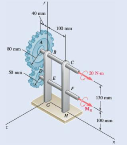
Fig. P6.159
(a)
The couple
Answer to Problem 6.159P
The couple
Explanation of Solution
Take all vectors along the
Radius of gear
Consider the projection of the gears on
The free body diagram of the Gear
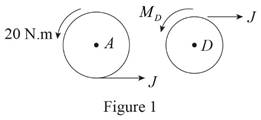
Here,
Write the expression for the moment at
Here,
Above equation implies that net moment at any point is the sum of product of each force acting on the system and perpendicular distance of the force and the point.
The moment at
Thus, write the complete expression of anticlockwise moment
Here,
At equilibrium, the sum of the moment acting at
Write the expression for the total anticlockwise moment acting at
Calculation:
Substitute
Substitute
Since the rotation is in the yz plane , the direction of couple is in
Therefore, the couple
(b)
The reaction at
Answer to Problem 6.159P
The point
Explanation of Solution
Free body diagram of Projection on
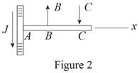
Here, is the tangential force acting on the gear,
From figure 2, write the equation of net moment about
Here,
Above equation implies that net moment at any point is the sum of product of each force acting on the system and perpendicular distance of the force and the point.
The moment at
Thus, write the complete expression of anticlockwise moment
Here,
At equilibrium, the sum of the moment acting at
Write the expression for the total anticlockwise moment acting at
Write the expression for the moment at
Here,
Above equation implies that net moment at any point is the sum of product of each force acting on the system and perpendicular distance of the force and the point.
At equilibrium, the sum of the moment acting at
Write the expression for the total anticlockwise moment acting at
Here,
The free body diagram of the projection on
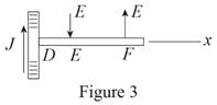
Here,
From figure 3, write the equation of net moment about
Here,
Above equation implies that net moment at any point is the sum of product of each force acting on the system and perpendicular distance of the force and the point.
The moment at
Thus, write the complete expression of anticlockwise moment
Here,
At equilibrium, the sum of the moment acting at
Write the expression for the total anticlockwise moment acting at
Write the expression for the moment at
Here,
Above equation implies that net moment at any point is the sum of product of each force acting on the system and perpendicular distance of the force and the point.
At equilibrium, the sum of the moment acting at
Write the expression for the total anticlockwise moment acting at
Here,
Consider the projection at
The free body diagram of the Bracket
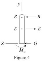
Here,
Write the expression for the total force along
Since in this direction net force is equal to zero. Equate above equation to zero.
Since total moment of force about
Write the equilibrium moment of force about
The free body diagram of the Bracket
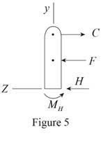
Here,
Write the expression for the total force along
Since in this direction net force is equal to zero. Equate above equation to zero.
Since total moment of force about
Write the equilibrium moment of force about
Calculation:
Substitute
Substitute
Substitute
Substitute
Substitute
Substitute
The negative sign indicate that it is directed along
Substitute
Substitute
The positive value indicate that it is directed along
Substitute
Therefore, the net force at
Want to see more full solutions like this?
Chapter 6 Solutions
Vector Mechanics for Engineers: Statics


- For the shown frame and loads P=756 KN and Q=1512 KN, - 3 m 1.5 m 1 m 8 m 6 m magnitude of y-component of reaction at B (KN) a. 168 b. 210 C. 252 d. 262.5 e. 294 magnitude of x-component of reaction at B (KN) a. 6552 b. 4368 с. 5460 d. 2184 e. 7644 magnitude of x-component of reaction at C (KN) magnitude of y-component of reaction at C (KN) magnitude of y-component of reaction at A (KN)arrow_forwardPROBLEM 6.84 Determine the components of the reactions at D and E if the frame is loaded by a clockwise couple of magnitude 150 N·m applied (a) at A, (b) at B. m -ns at A and 'C 0.4 m 0.4 m A B C -0.6 m 0.6 m - D -0.6 m Earrow_forwardFor the shown frame and loads P=972 KN and Q=1944 KN, 3 m 3 m→ B 1.5 m A 1 m 8 m 6 m magnitude of y-component of reaction at B (KN) a. 216 b. 270 c. 324 d. 337.5 е. 378 magnitude of x-component of reaction at B (KN) a. 5616 b. 2808 c. 7020 d. 8424 e. 9828 magnitude of x-component of reaction at C (KN) magnitude of y-component of reaction at C (KN) magnitude of y-component of reaction at A (KN)arrow_forward
- The lid of a roof scuttle weighs 75 lb. It is hinged at corners A and B and maintained in the desired position by a rod CD pivoted at C; a pin at end D of the rod fits into one of several holes drilled in the edge of the lid. For α=50°, determine (a) the magnitude of the force exerted by rod CD, (b) the reactions at the hinges. Assume that the hinge at B does not exert any axial thrust.arrow_forwardFor the given loads w = 28 KN/m and M=70 KN.m is supported as shown by a roller at D and a hinge at D W kN/m M kN - m 1m- 3 m- 2 m Magnitude of reaction at D is (KN) а. 56 b. 140 c. 112 d. 168 e. 196 Magnitude of reaction at A is (KN) а. 126 b. 168 c. 112 d. 56 е. 28 Shear force just to the right of D Shear force just to the left of D Bending moment just to the right of B (KN.m) a. -28 b. -42 C. -56 d. -70 e. -84 Maximum absolute value of bending moment (KN.m) isarrow_forwardFor the given loads w = 28 KN/m and M=70 KN.m is supported as shown by a roller at Dand a hinge at D W kN/m M kN - m 1m- 3 m- Magnitude of reaction at D is (KN) а. 56 b. 140 c. 112 d. 168 e. 196 Magnitude of reaction at A is (KN) а. 126 b. 168 c. 112 d. 56 е. 28 Shear force just to the right of D 56 Shear force just to the left of D -56 Bending moment just to the right of B (KN.m) a. -28 b. -42 C. -56 d. -70 e.-84 Maximum absolute value of bending moment (KN.m) is Please put a in each input field.arrow_forward
- A uniform semi-circular rod of weight 20 N and radius 12 cm is attached to a pin at A and rests against a frictionless surface at B. Determine the reaction at A. a.21 N b.12 N c.6.4 N d.2.1 Narrow_forwardA thin rod AB of length 1 = 600 mm is connected to a sliding sleeveon a pole. The rod rests on a C-shaped wheel located at a distancehorizontal a = 80 mm from the vertical axis of the post. Knowing that us = 0.25between the sleeve and the post, that the radius of the wheel is negligible, thatG= 100 N and 0 = 30°, determine the range of values of P ensuringthe balance of the assemblyarrow_forwardArm ABC is connected by pins to a collar at B and to crank CD at C Neglecting the effect of friction, determine the couple M required to hold the system in equilibrium 'when 0= 0.Fig.P6.133arrow_forward
- A sign of weight 2280 N is supported as shown by a ball and socket support at A and two cables BC and AD 1- Tension in cable BC is (N) : (a. 4560 - b. 6840 - c. 5700 - d. 7980 - e. 9120 ) 2- Tension in cable AD is (N): (a. 10260 - b. 13680 - c. 15960 - d. 18240 - e. 10640 ) 3-Magnitude of x-component of reaction at O is (N): (a. 5700 - b. 6840 - c. 7980 - d. 9120 - e. 10260 ) 4- Find Magnitude of y-component of reaction at O is (N) 5- Find Magnitude of z-component of reaction at O is (N)arrow_forwardKnowing that for the rod of Prob. 4.89, L = 15 in., R = 20 in., and W = 10 lb, determine (a) the angle 0 corresponding to equilibrium, (b) the reactions at A and B.(Reference to Problem 4.89):A slender rod with a length of L and weight W is attached to a collar at A and is fitted with a small wheel at B . Knowing that the wheel rolls freely along a cylindrical surface of radius R , and neglecting friction, derive an equation in 0, L, and that must be satisfied when the rod is in equilibrium.arrow_forwardSolve Prob. 4.113, assuming that the hinge at A has been removed and that the hinge at B can exert couples about axes parallel to the x and y axes.(Reference to Problem 4.113):A 10-kg storm window measuring 900 × 1500 mm is held by hinges at A and B . In the position shown, it is held away from the side of the house by a 600-mm stick CD . Assuming that the hinge at A does not exert any axial thrust, determine the magnitude of the force exerted by the stick and the components of the reactions at A and B.arrow_forward
 Elements Of ElectromagneticsMechanical EngineeringISBN:9780190698614Author:Sadiku, Matthew N. O.Publisher:Oxford University Press
 Mechanics of Materials (10th Edition)Mechanical EngineeringISBN:9780134319650Author:Russell C. HibbelerPublisher:PEARSON
 Thermodynamics: An Engineering ApproachMechanical EngineeringISBN:9781259822674Author:Yunus A. Cengel Dr., Michael A. BolesPublisher:McGraw-Hill Education
 Control Systems EngineeringMechanical EngineeringISBN:9781118170519Author:Norman S. NisePublisher:WILEY
 Mechanics of Materials (MindTap Course List)Mechanical EngineeringISBN:9781337093347Author:Barry J. Goodno, James M. GerePublisher:Cengage Learning
 Engineering Mechanics: StaticsMechanical EngineeringISBN:9781118807330Author:James L. Meriam, L. G. Kraige, J. N. BoltonPublisher:WILEY