
Videos
6.119 through 6.121 Each of the frames shown consists of two L-shaped members connected by two rigid links. For each frame, determine the reactions at the supports and indicate whether the frame is rigid.
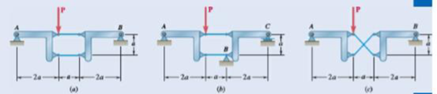
Fig. P6.121
The reactions at the frame and the rigidness of the frame.
Answer to Problem 6.121P
The reactions at the frame for figure (a) is
Explanation of Solution
The following figure gives the free body diagram of the first part of the member in figure P6.121(a).
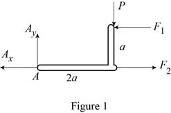
Write the equation to find the moment of force.
Here,
Write the equation to find the total moment about the point
Write the equations for equilibrium for the free body diagram in figure 1.
Here,
The following figure gives the free body diagram of the second part of the member in figure P6.121(a).
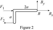
Write the equations for equilibrium for the free body diagram in figure 2.
Here,
The following figure gives the free body diagram of the first part of the member in figure P6.119(b).
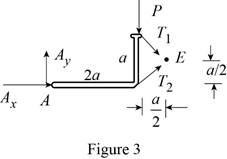
Write the equations for equilibrium for the free body diagram in figure 3.
Here,
The following figure gives the free body diagram of the second part of the member in figure P6.119(b).
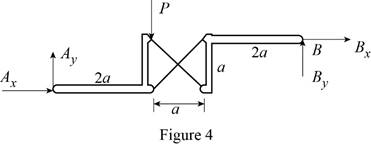
Write the equations for equilibrium for the free body diagram in figure 4.
Here,
The following figure gives the free body diagram of the member in figure P6.119(c).
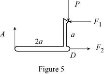
Write the equations for equilibrium for the free body diagram in figure 5.
Here,
The following figure gives the free body diagram of right part of the member in figure P6.119(c).
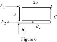
Write the equations for equilibrium for the free body diagram in figure 6.
Here,
Write the expression to find the magnitude of the vector from its components.
Here,
Write the equation to find the angle of orientation of the vector
Conclusion:
Solve equation (I) using figure 1.
Rewrite the above equation.
Solve equation (III) using figure 1.
Rewrite the above equation.
Solve equation (IV) using figure 2.
Rewrite the above equation.
Solve equation (V) using figure 2.
Substitute
Solve equation (VI) using figure 2.
Substitute
Rewrite equation (XIV) in terms of the vector
Substitute
Rewrite equation (XV) in terms of the vector
Substitute
Rewrite equation (XIV) in terms of the vector
Substitute
Solve equation (VII) using figure 3.
Rewrite the above equation.
Solve equation (VIII) using figure 4.
Rewrite the above equation.
Solve the conditions obtained from figure 3 and 4.
Solve equation (IX) using figure 5.
Rewrite the above equation to find
Solve equation (X) using figure 5.
Substitute
Solve equation (XI) using figure 5.
Substitute
Solve equation (XII) using figure 6.
Substitute
Solve equation (XII) to the right using figure 6.
Substitute
Solve equation (XII) upwards using figure 6.
Substitute
Therefore, the reactions at the frame for figure (a) is
Want to see more full solutions like this?
Chapter 6 Solutions
Vector Mechanics for Engineers: Statics


- The assembly shown consists of an 80-mm rod AF that is welded to a cross frame consisting of four 200-mm arms. The assembly is supported by a ball-and-socket joint at F and by three short links, each of which forms an angle of 45° with the vertical. For the loading shown, determine (a) the tension in each link, (b) the reaction at F.arrow_forwardThe axis of the three-hinge arch ABC is a parabola with vertex at B.Knowing that P= 112 kN and Q =140 kN, determine (a) the components of the reaction at A, (b) the components of the force exerted at B on segment AB.arrow_forwardThe axis of the three-hinge arch ABC is a parabola with vertex at B . Knowing that P= 112 kN and Q = 140 kN, determine (a) the components of the reaction at A, (b) the components of the force exerted at B on segment AB.arrow_forward
- 6.53 A Pratt roof truss is loaded as shown. Determine the force in members CE, DE, and DF. 3 kN 3 kN 3 kN 3 kN 3 kN 1.5 kN 6.75 m L5 kN B C 3 m 3 m 3 m 3 m 3 m 3 m Fig. P6.53 and P6.54arrow_forwardSolve Prob. 4.115, assuming that the hinge at A has been removed and that the hinge at B can exert couples about axes parallel to the x and y axes.(Reference to Problem 4.115):The horizontal platform ABCD weighs 60 lb and supports a 240-lb load at its center. The platform is normally held in position by hinges at A and B and by braces CE and DE. . If brace DE is removed, determine the reactions at the hinges and the force exerted by the remaining brace CE . The hinge at A does not exert any axial thrust.arrow_forwardPROBLEM 6.84 Determine the components of the reactions at D and E if the frame is loaded by a clockwise couple of magnitude 150 N·m applied (a) at A, (b) at B. m -ns at A and 'C 0.4 m 0.4 m A B C -0.6 m 0.6 m - D -0.6 m Earrow_forward
- The T-shaped bracket shown is supported by a small wheel at E and pegs at C and D . Neglecting the effect of friction, determine (a) the smallest value of 0 for which the equilibrium of the bracket is maintained, (b) the corresponding reactions at C, D, and E.arrow_forwardThe press shown below is used to emboss a small metal plate at E. The press is composed of 3 members: handle ABC, link BD, and piston DE that are connected by pins at points A, B. and D. A vertical force of 250 N is applied at point C. Determine: (a) The vertical component of the force exerted on the plate at E and the reactions at pin A. (b) The mechanical advantage of the press. Draw all required FBD's and put units on your answers. A 200 mm 60° 19T 20° 400 mm 15⁰ C C Parrow_forwardA slender bar of length L = 400 mm is held in equilibrium, with one end touching a frictionless wall and the other end attached to a wire of length S = 600 mm as illustrated. Knowing that the weight of the bar is 147 N (which acts at the mid-length of the bar), determine: a. the distance h. b. the tension in the wire. c. the reaction at B. C. Вarrow_forward
- 6.1 through 6.8 Using the method of joints, determine the force in each member of the truss shown. State whether ch member is in tension or compression. 375 lb A 8 ft 500 lb В C O D 8.4 ft Fig. P6.4arrow_forwardA 200-kg crate is to be supported by the rope-and-pulley arrangement shown. Determine the magnitude and direction of the force P that must be exerted on the free end of the rope to maintain equilibrium. (Hint: The tension in the rope is the same on each side of a simple pulley. This can be proved by the methods of Chap. 4.)arrow_forwardThe bent rod ABEF is supported by bearings at C and D and by wire AH. Knowing that portion AB of the rod is 250 mm long, determine;a) The tension in the wire AH.b) Reactions at C and D.Assume that the bearing at D does not exert a force ofaxial thrust. (need free body diagrams)arrow_forward
 Elements Of ElectromagneticsMechanical EngineeringISBN:9780190698614Author:Sadiku, Matthew N. O.Publisher:Oxford University Press
 Mechanics of Materials (10th Edition)Mechanical EngineeringISBN:9780134319650Author:Russell C. HibbelerPublisher:PEARSON
 Thermodynamics: An Engineering ApproachMechanical EngineeringISBN:9781259822674Author:Yunus A. Cengel Dr., Michael A. BolesPublisher:McGraw-Hill Education
 Control Systems EngineeringMechanical EngineeringISBN:9781118170519Author:Norman S. NisePublisher:WILEY
 Mechanics of Materials (MindTap Course List)Mechanical EngineeringISBN:9781337093347Author:Barry J. Goodno, James M. GerePublisher:Cengage Learning
 Engineering Mechanics: StaticsMechanical EngineeringISBN:9781118807330Author:James L. Meriam, L. G. Kraige, J. N. BoltonPublisher:WILEY