What are limits or limits of size?
The maximum or minimum allowable sizes within which the size of component lies are known as limits. The limits are classified into two types:
- Upper limit
- Lower limit
Upper limit
The maximum permissible size or largest acceptable size of the component is called the upper limit of size.
Lower limit
The minimum permissible size or smallest acceptable size of the component is called the lower limit of size.
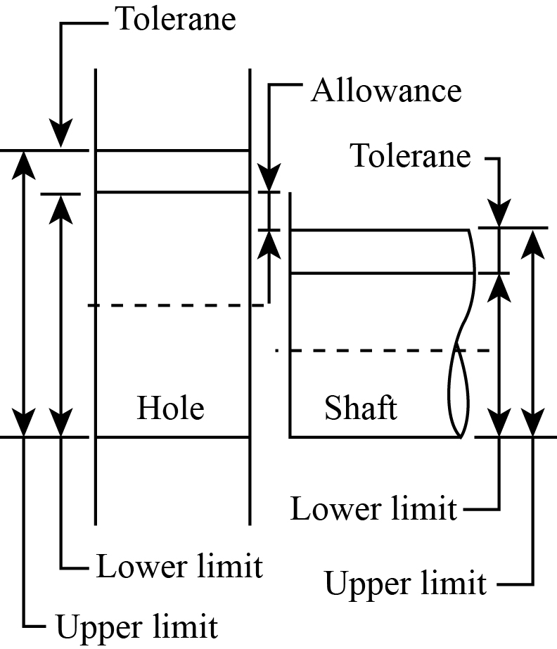
The diagrammatical representation of limits of size is shown as:
Nominal or basic size
The nominal size is described as the size of the component about which the limits are fixed. It is also termed as basic size or size of zero deviation.
Example - Shaft has to be manufactured to the diameter of
20±0.02.
Solution: The basic size of the shaft is 20 mm and it is acceptable if its diameter lies between the limits of size.
The upper limit of the shaft diameter is given as,
The lower limit of the shaft diameter is given as,
Therefore, the upper limit and lower limit of the shaft diameter are 20.02 mm and 19.98 mm respectively.
Tolerance
Tolerance is described as the difference between the upper and lower limit. It is also defined as the difference between the maximum and minimum limits of size for the component. The tolerance is classified into two types:
- Unilateral tolerance
- Bilateral tolerance
Example: Hole has to be drilled to the diameter of
.
Solution: The basic size of the hole is 10 mm and it is acceptable if its diameter lies between the limits of size.
The upper limit for the diameter of the hole is given as,
The lower limit for the diameter of the hole is given as,
The tolerance of the hole is given as,
Thus, the tolerance of the hole is 0.04 mm.
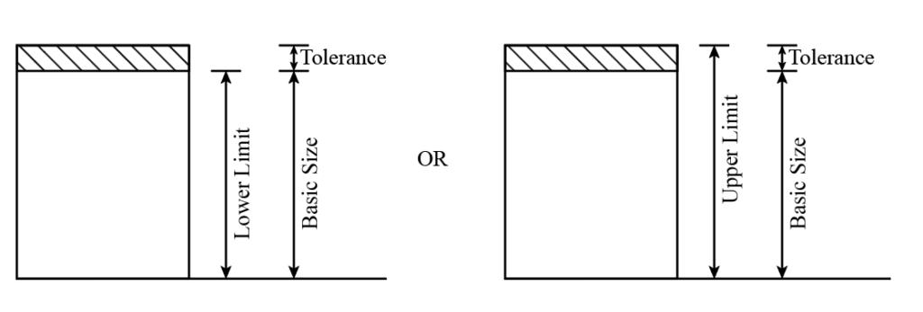
Unilateral tolerance
Unilateral tolerance is described as the tolerance that allows variation in only one direction from the basic or nominal size. In unilateral tolerance, the size of the component is always either small or large from its basic size.
In unilateral tolerance, both upper and lower limits are either above or below the basic size of the component.
Example:
The diagrammatical representation of the unilateral tolerance is shown as:
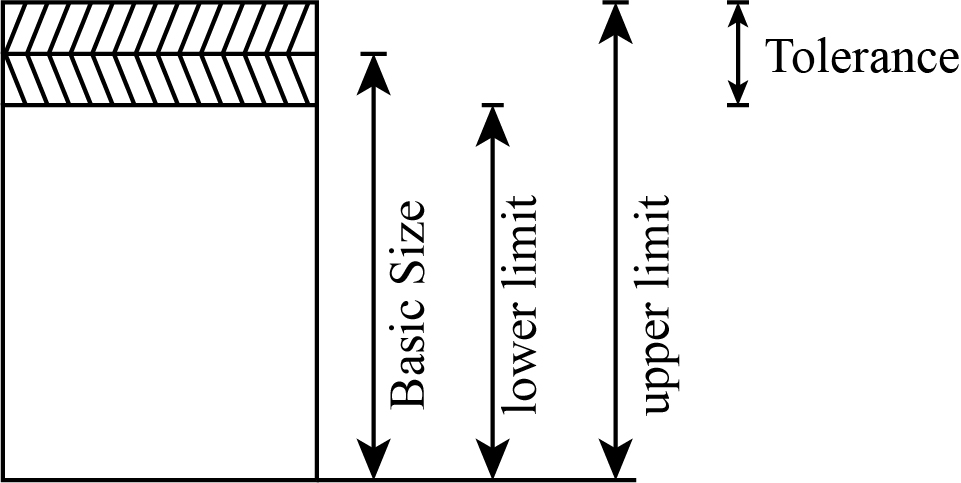
Bilateral tolerance
Bilateral tolerance is described as the tolerance that allows variation in both directions from the basic or nominal size. In unilateral tolerance, the size of the component may be small or large from its basic size. In bilateral tolerance, the maximum limit is above the basic size, and the minimum limit is below the basic size.
The combined plus or minus symbol is used with a single value to specify an equal variation in both directions.
Example:
The diagrammatical representation of the bilateral tolerance is shown as:
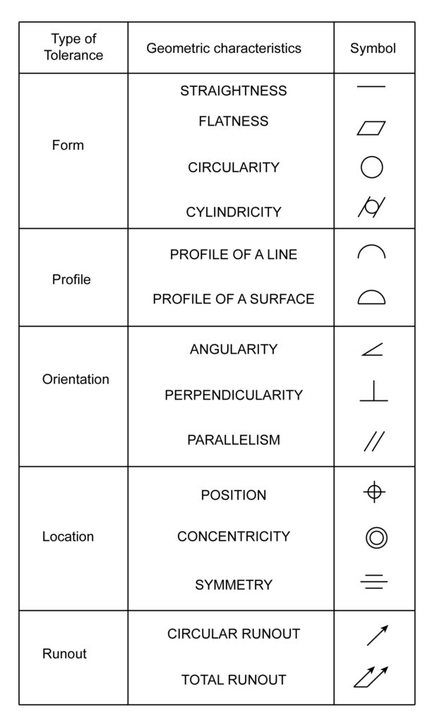
What are geometric tolerances?
Geometric tolerances are specified as the allowable variation of the shape of a component. It is different from the tolerances allowed for the size of the component.
Geometric tolerances are divided into three types:
- Form
- Orientation
- Position tolerances
The diagram shown below represents the type, characteristic, and symbol of geometric tolerances:
Fits
A fit is described as a relative motion between the components, generally hole and shaft resulting from their size achieved during their manufacturing.
It is also defined as the degree of looseness or tightness among two mating parts.
Following are the classification of fits based on the combination between shaft and hole:
- Clearance fit
- Transition fit
- Interference fit
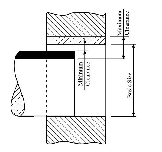
Clearance fit
The clearance fit results when the shaft size is always less than the hole size for all possible combinations lying in the tolerance range.
In a clearance fit, the relative motion between the shaft and hole is always possible. In this, the lower limit size of the hole is greater or equal to the upper limit size of the shaft.
The minimum clearance is obtained at the maximum shaft size and the minimum hole size in the clearance fit. In contrast, the maximum clearance is obtained at the minimum shaft size and the maximum hole size.
The diagrammatical representation of the clearance fit is shown as:
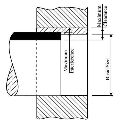
Transition fit
The transition fit results when the shaft and hole are precisely the exact sizes.
It is a boundary between clearance and interference and is achieved practically with selective assembly or careful machining methods within very few limits.
The practical transition fits occur when the tolerance is so that the largest hole is greater than the smallest shaft and the largest shaft is greater than the smallest hole.
In transition fit, the relative motion between shaft and hole is possible when clearance exists but not possible when interference exists.
The diagrammatical representation of the transition fit is shown as:
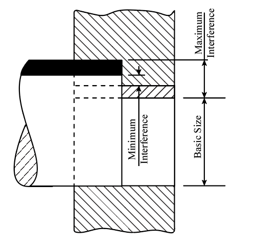
Interference fit
The interference fit results in the minimum shaft size being larger than the maximum hole size for all possible combinations in the given range. In interference fit, the relative motion between the shaft and hole is impossible.
The maximum interference occurs at the minimum shaft size and maximum hole size in an interference fit. In contrast, the maximum interference occurs at the maximum shaft size and minimum hole size.
The diagrammatical representation of the interference fit is shown as:
Important terms related to limits, fits, and tolerances
Allowance
The allowance is described as the difference between the maximum material limit of the mating parts or holes and the shaft. The minimum clearance is called a positive allowance, and maximum interference is called a negative allowance.
The maximum material limit is defined as the maximum shaft size and minimum hole size. Hence, the difference between them is the maximum interference or minimum clearance. i.e.,
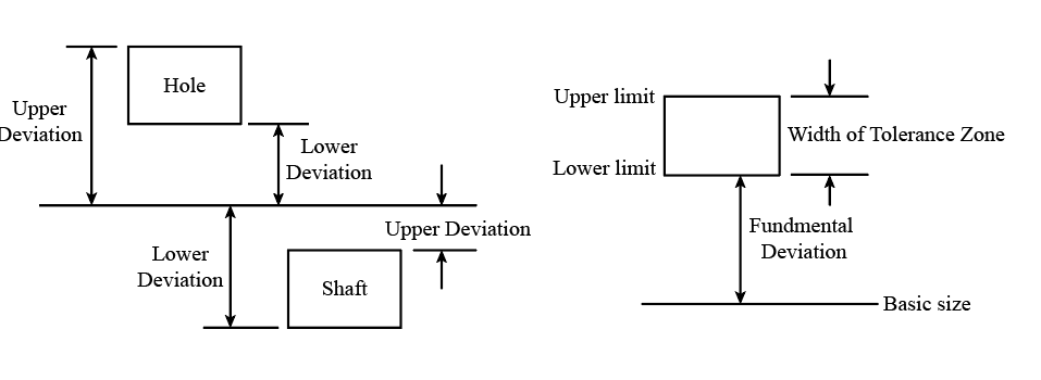
Fundamental deviation
The fundamental deviation is described as the distance from the basic size to the tolerance zone. The diagrammatical representation of fundamental deviation is shown as:
Common Mistakes
Following are the common mistakes performed by students:
- Sometimes, students get confused between allowance and tolerance.
- Sometimes, students forget the concept of geometric tolerances.
- Sometimes, students get confused between interference and transition fits.
- Sometimes, students are confused between positive and negative allowance.
Context and Applications
The topic of limits fits, and tolerances are significant in various courses and professional exams of undergraduate, graduate, postgraduate, doctorate levels. For example:
- Diploma in Mechanical Engineering
- Bachelor of Technology in Mechanical Engineering
- Bachelor of Technology in Production Engineering
- Bachelor of Technology in Instrumental Engineering
- Bachelor of Technology in Petroleum Engineering
- Master of Technology in Production Engineering
Related Concepts
- Measuring instruments
- Metrology
- Design of limit gauges
- Quality control
Practice Problems
Q1. Which of the following limit is called a zero-deviation limit?
- Upper limit
- Lower limit
- Nominal or basic limit
- None of these
Correct option: (c)
Explanation: The zero deviation limit is considered the basic limit. It is described as the zero line. Any deviations can be considered above or below the zero line. When any deviations are zero, then they can be defined accordingly as basic shaft and basic hole.
Q2. A tolerance that allows variation in both directions from the basic size is ______?
- Unilateral tolerance
- Bilateral tolerance
- Geometric tolerance
- All of the above
Correct option: (b)
Explanation: When the variations are in both directions, they are termed Bilateral tolerance. There are equal variations (deviations) on each side of the part. Tolerance can be unilateral, bilateral, geometric tolerance.
Q3. is an example of which tolerance?
- Unilateral tolerance
- Bilateral tolerance
- Geometric tolerance
- None of these
Correct option: (a)
Explanation: This type of tolerance is known as unilateral tolerance. Here the deviation of the part is in one direction only. So, the upper limit is only given in the specification of the part size.
Q4. Which of the following fit results when the shaft and hole are precisely the exact sizes?
- Clearance fit
- Transition fit
- Interference fit
- Both transition and interference fit
Correct option: (b)
Explanation: Transition fit is defined as the width of the inner part of any work piece as the same as that of the hole in which it will be inserted. Transition fit is employed where an accurate location is required.
Q5. Negative allowance is also termed as?
- Maximum clearance
- Minimum clearance
- Maximum interference
- Minimum interference
Correct option: (c)
Explanation: Negative allowance is also known as maximum interference. It is defined as the difference between minimum hole size and the maximum shaft size just before assembly. It can also be defined as the subtraction of the lower limit of the hole from the upper limit of the shaft.
Want more help with your mechanical engineering homework?
*Response times may vary by subject and question complexity. Median response time is 34 minutes for paid subscribers and may be longer for promotional offers.
Search. Solve. Succeed!
Study smarter access to millions of step-by step textbook solutions, our Q&A library, and AI powered Math Solver. Plus, you get 30 questions to ask an expert each month.
Manufacturing Engineering and Technology
Metrology and Measurements
Limits, Fits and Tolerances
Limits, Fits, and Tolerances Homework Questions from Fellow Students
Browse our recently answered Limits, Fits, and Tolerances homework questions.
Search. Solve. Succeed!
Study smarter access to millions of step-by step textbook solutions, our Q&A library, and AI powered Math Solver. Plus, you get 30 questions to ask an expert each month.