
Mechanics of Materials (MindTap Course List)
9th Edition
ISBN: 9781337093347
Author: Barry J. Goodno, James M. Gere
Publisher: Cengage Learning
expand_more
expand_more
format_list_bulleted
Related questions
Question
7
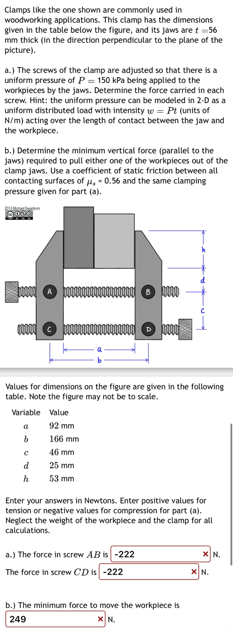

Transcribed Image Text:Clamps like the one shown are commonly used in
woodworking applications. This clamp has the dimensions
given in the table below the figure, and its jaws are t =56
mm thick (in the direction perpendicular to the plane of the
picture).
a.) The screws of the clamp are adjusted so that there is a
uniform pressure of P =
= 150 kPa being applied to the
workpieces by the jaws. Determine the force carried in each
screw. Hint: the uniform pressure can be modeled in 2-D as a
uniform distributed load with intensity w = Pt (units of
N/m) acting over the length of contact between the jaw and
the workpiece.
b.) Determine the minimum vertical force (parallel to the
jaws) required to pull either one of the workpieces out of the
clamp jaws. Use a coefficient of static friction between all
contacting surfaces of µs = 0.56 and the same clamping
pressure given for part (a).
2013 Michael Swanbom
BY NC SA
A
B
с
C
D
a
Values for dimensions on the figure are given in the following
table. Note the figure may not be to scale.
Variable Value
a
92 mm
b
166 mm
с
46 mm
d
25 mm
h
53 mm
Enter your answers in Newtons. Enter positive values for
tension or negative values for compression for part (a).
Neglect the weight of the workpiece and the clamp for all
calculations.
a.) The force in screw AB is -222
The force in screw CD is -222
b.) The minimum force to move the workpiece is
249
☑ N.
× N.
☑ N.
Expert Solution
This question has been solved!
Explore an expertly crafted, step-by-step solution for a thorough understanding of key concepts.

Step by stepSolved in 2 steps with 1 images

Knowledge Booster

Similar questions
- An inflatable structure used by a traveling circus has the shape of a half-circular cylinder with closed ends (see figure). The fabric and plastic structure is inflated by a small blower and has a radius of 40 ft when fully inflated. A longitudinal scam runs the entire length of the "ridge" of the structure. If the longitudinal scam along the ridge tears open when it is subjected to a tensile load of 540 pounds per inch of seam, what is the factor of safety n against tearing when the internal pressure is 0,5 psi and the structure is fully inflated?arrow_forward56 Clamps like the one shown are commonly used in woodworking applications. This clamp has the dimensions given in the table below the figure, and its jaws are mm thick (in the direction perpendicular to the plane of the picture). a.) The screws of the clamp are adjusted so that there is a uniform pressure of P = 150 kPa being applied to the workpieces by the jaws. Determine the force carried in each screw. Hint: the uniform pressure can be modeled in 2-D as a uniform distributed load with intensity w = Pt (units of N/m) acting over the length of contact between the jaw and the workpiece. b.) Determine the minimum vertical force (parallel to the jaws) required to pull either one of the workpieces out of the clamp jaws. Use a coefficient of static friction between all contacting surfaces of μs = 0.56 and the same clamping pressure given for part (a). 2013 Michael Swanbom A B C a Values for dimensions on the figure are given in the following table. Note the figure may not be to scale.…arrow_forwardClamps like the one shown are commonly used in woodworking applications. This clamp has the dimensions given in the table below the figure, and its jaws aret = 49 mm thick (in the direction perpendicular to the plane of the picture). a.) The screws of the clamp are adjusted so that there is a uniform pressure of P = 115 kPa being applied to the workpieces by the jaws. Determine the force carried in each screw. Hint: the uniform pressure can be modeled in 2-D as a uniform distributed load with intensity w = Pt (units of N/m) acting over the length of contact between the jaw and the workpiece. b.) Determine the minimum vertical force (parallel to the jaws) required to pull either one of the workpieces out of the clamp jaws. Use a coefficient of static friction between all contacting surfaces of us = 0.4 and the same clamping pressure given for part (a). 2013 Michael Swanbom BY NC SA d 0000 O bo 0000000 P b. Values for dimensions on the figure are given in the following table. Note the…arrow_forward
- a b c d h 82 mm 139 mm 39 mm 18 mm 33 mm Clamps like the one shown are commonly used in woodworking applications. This clamp has the dimensions given above, and its jaws are 38 mm wide (in the direction perpendicular to the plane of the picture). The screws of the clamp are adjusted so that there is a uniform pressure of 190 kPa being applied to the workpieces by the jaws. Find the force carried in each screw.Note: Assume that A, B, C, and D act as pins. (Denote tension forces with positive values; compressive forces with negative values.)arrow_forward4.As shown in the figure, a square threaded screw is used in a vise to exert a pressure of 2 tons. If the screw is double-threaded and has a pitch of 0.25 m and a mean radius of 1.5 inch, determine the torque that must be applied at B to create this pressure. Assume the coefficient of friction to be 0.15. Parrow_forwardQ1: The arrangement of a transmission brake is shown in the figure. The arms are pivoted at O and, when force is applied at the end of the hand lever, the screw AB will rotate. The left-and right- hand threads working in nuts on the ends of the arms will move the arms together and thus apply the brake actuating force equally. A B 12cm The drum is 17.75cm diameter, and the angle subtended by each block is 90°. the friction material lining width is 4cm. Assuming a coefficient of friction for the braking surfaces that is equal to 0.30 Determine the force required by the screw AB to set the brake torque on the drum equal to 200 N-m. 17 75cm 12cm 46 35cm Torqueleft= TorqueRight= 97.40 N.m 6 35cm 102.60 N.marrow_forward
- For the nose landing gear of an aircraft shown in the figure, calculate the internalforces at the vertical section at point A.arrow_forwardDetermine the magnitude of the clamping forces (in pounds) exerted on the nut along line aa when two 64-lb forces are applied to the handles, as shown in the figure. Assume bolts A and D slide freely in the jaw slots.arrow_forwardProblem: The steel pipe has an inner diameter of 2.75 in and an outer diameter of 3 in. The pipe is fixed to the ground at C, and a wrench is attached to the opposite end. The wrench is subjected to a horizontal force of 20 lb that acts in -z direction. Points A and B are located on the surface of the pipe at the same cross section. Note that A lies directly above the -y axis, and B lies directly above the +z axis. 20 lb 10 in. A B y 12 in. (a) Find the normal and shear stresses at points A and B. (b) Find the principal stresses at points A and B. (c) Show all stresses from parts (a) and (b) on properly oriented elements, relative to the given coordinate system.arrow_forward
- Compute the tensile stress for the rod shown in Fig. 1 at section A-A, the shearing stress across section B, the compressive stress between the pin and the rod, and the compressive stress between the pin and the yoke. Given n = 1 (3 / 4) in., a = (15 / 32) in., e = (27 / 32) in., b = (15 / 16) in., d = (19 / 32) in., f = 1".arrow_forwardPlease help. Written on paper not typed on computer or keyboard please. Need help on both questions. Please include all units, steps to the problem and information such as its direction or if it is in compression or tension. Thx.arrow_forwardAn ACME-thread power screw is considered. The coefficient of friction of the thread is mu. The external load on the screw is F. d = 1.75; % (in) major diameter | = 0.25; % (in) screw lead mu = 0.2; % coefficient of friction for thread F = 2000; % (lb) external load on the screw Find: 2.4 the moment required for lowering the load (Ib in)arrow_forward
arrow_back_ios
SEE MORE QUESTIONS
arrow_forward_ios
Recommended textbooks for you
- Mechanics of Materials (MindTap Course List)Mechanical EngineeringISBN:9781337093347Author:Barry J. Goodno, James M. GerePublisher:Cengage Learning
 International Edition---engineering Mechanics: St...Mechanical EngineeringISBN:9781305501607Author:Andrew Pytel And Jaan KiusalaasPublisher:CENGAGE L
Mechanics of Materials (MindTap Course List)
Mechanical Engineering
ISBN:9781337093347
Author:Barry J. Goodno, James M. Gere
Publisher:Cengage Learning
International Edition---engineering Mechanics: St...
Mechanical Engineering
ISBN:9781305501607
Author:Andrew Pytel And Jaan Kiusalaas
Publisher:CENGAGE L