What is a PID Controller?
PID (Proportional Integrator Derivative) the controller is an instrument used to regulate the temperature, pressure, flow, speed, and other process parameters in the industry. It uses a closed-loop feedback system to regulate control parameters to achieve the output value as near to the setpoint or set possible value. It is considered an accurate and stable controller in the control system. Most of the control system theories use PID control for their control action method. The overall control function Gc(s) can be written as
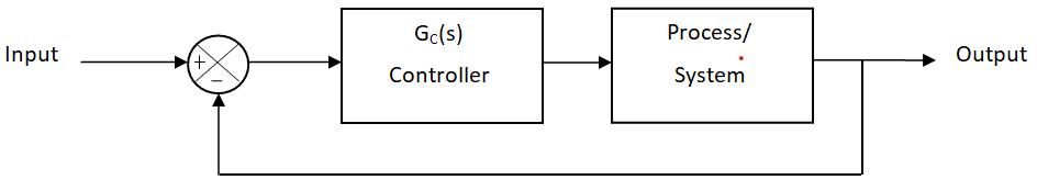
Where Kp, Ki and KD denote the coefficients of proportional, integral and derivative terms respectively. They are all positive coefficients. TI and TD represent the integral and derivative time respectively. The concept of PID-controller was evolved by Elmer Sperry in 1911 after rigorous research. The Taylor Instrument company built the Pneumatic control in 1933. This Pneumatic PID was developed by a derivative term to overcome the overshoot problem. Between 1942 to mid-1950, the researcher was able to invent perfect tuning of the PID controller for industrial automation with the help of Ziegler and Nichols tuning rules. Those tuning rules had a tremendous hike on the use of PID in the control system area. After the 1950s the PID controller was adopted for industrial use. More than 90 % of the control loops are PID.
How does the PID Controller work?
The purpose of this type of controller is to maintain the setpoint through feedback. For example, we consider an Oven that is equipped with the PID Control. The Oven is set to Turn ON and Turn OFF at predefined temperatures. The PID Controller is very much sensitive to small changes, and quickly reacts OR responds to that change. To have an idea of how the working of the PID controller is we first need to touch upon the individual function of Proportional, integral, and derivative tuning. All the controller has its Pros and Cons with that they are decided for the use in different applications.
Proportional Controller
As the name suggests proportionally, the output (actuating signal) of the system is directly proportional to the error signal. Two conditions need to be fulfilled for the application which is as follows; (1) the derivative between input and output should be small. (2) There should not be any sudden derivative. It helps in reducing the steady-state error and makes the controller stable. The response of the overdamped system can be made faster using P-type controllers.
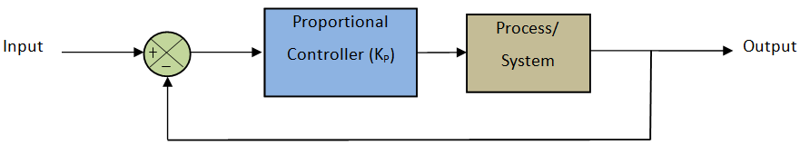
Where Kp is the coefficient of proportional term.
Integral Controller
In this, the steady-state error that occurs in the proportional controller is eliminated. The first order original transfer function is changed to the second-order in feedback configuration with an integral controller. Because of the continuous change in the control action, this controller is also known as a reset controller.
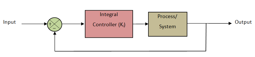
Where Ki is the coefficient of integral term.
Derivative controller
The Problem of Stability and overshoot arises with the use of a P controller with higher gain. This problem can be encountered by adding a time derivative to the error signal. The D controller should be coupled with the P OR I controller for proper function.
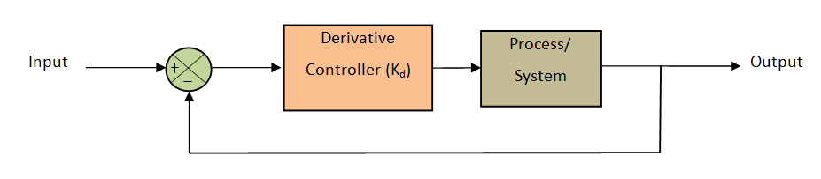
Where Kd is the coefficient of derivative term.
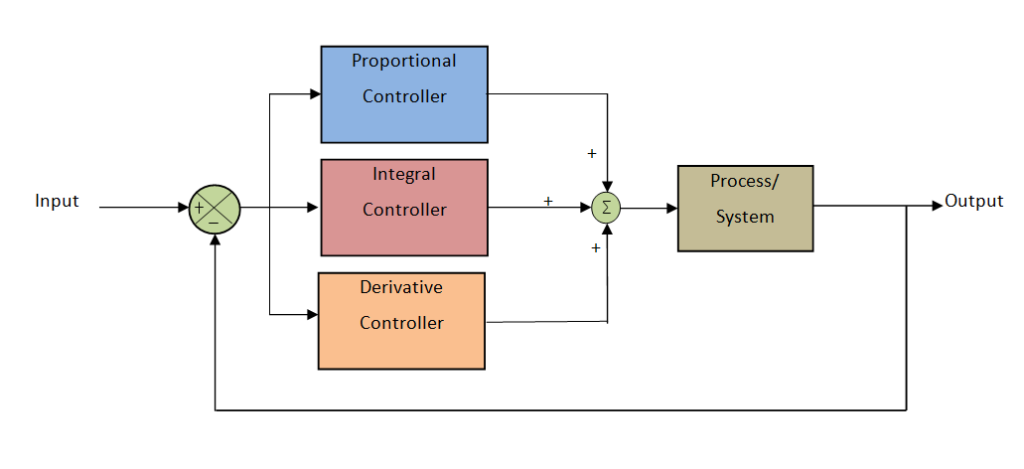
PID Controller
It is a combination of all three controllers (Proportional Integrator Derivative) which overcomes the disadvantages of each other and makes the controller stable, accurate, and more responsive. It comprises a quicker response time as of the P-only control, laterally with the decreased/zero offset from the joint derivative and integral controllers. The offset was detached by using the I control. The accumulation of D-control greatly increases the controller's retort when used in combination because it forecasts disturbances to the system by measuring the variation in error. On the contrary, as mentioned previously, when used alone, it has a sluggish response time compared to the quicker P control. However, although the PID seems to be the most satisfactory controller, it is also the classiest controller. Therefore, it is not used unless the process needs the accuracy and stability provided by the PID controller. A PID controller is used only when accuracy and stability is required. It has difficulties in the presence of non-linearity. The system starts getting irregular on-time response and behavior and also lags to respond to large disturbances. Overshoot Parameter needs to be adjusted in PID control by tuning methods. The performance of the closed-loop control OR response of the PID depends upon the parameter of PID which is given in the below table. This type of PID controller is designed using MATLAB software.
| Parameters | Overshoot | Rise time | Settling time | SSE | Stability |
| Kp | Increase | Decrease | Small Effect | Decrease | Degrade |
| Ki | Increase | Decrease | Increase | Eliminate | Degrade |
| Kd | Decrease | Minor Effect | Decrease | No effect | Improve If Kd is small |
Tuning Methods
It has a model-based tuning method for numerical optimization. Before the PID controller works, it must be consistent with the process being dynamic because the controlled designers give default values of the object's conditions and those values may not give the wanted performance and every so often instability and flow control give rise to the recital of the control system. A variety of tuning approaches are established for PID controllers and require a boundless deal of consideration from the operator to select the finest values of proportional-integral & derivative gain. The Required output of the PID controller can be gained by tuning the controller which is a part of the PID controller design. There are different procedures available to get the desired output from the PID like the trial-and-error method, Zeigler-Nichol’s technique, and the Process reaction curve method. The most often used tuning practices are trial and error and Zeigler Nichols.
Trial & Error Method : This is a simple way of PID controller tuning. Though the control system or PID controller is working, the controller can be tuned. In this technique, initially, we have to set two values (Ki and Kd parameter) to zero and further increase the proportional term (Kp) until the system reaches oscillating behaviour. Once it is oscillating, adjust the value of Ki the Integral term so that oscillations stop, and then lastly adjust the parameters D for the fast response.
Zeigler-Nichols method : It is used for tuning the PID controller. It is a closed-loop method. It is also termed as continuous cycling method OR damped oscillation method. Actions for both the methods are the same but oscillatory behavior is different. In this, initially, we have to set the P-controller constant and Kp to a specific value while Ki and Kd parameters are zero. Proportional gain is improved till the system oscillates at a constant amplitude. The system that produces constant oscillations at a particular gain is called ultimate gain (Ku) and the period of oscillations is called the ultimate period (Pc). Once it is reached, we can enter the parameters of P I D in the PID controller.
Context and Application
In the old day’s machines were equipped with monitoring devices for smooth operation such as temperature gauge, pressure gauge, low gauge, etc (all analogy meters). At that time industries are required to appoint an operator who will monitor those monitoring devices and adjust the values, but the time passes that the industry started adopting digital meters and with it the PIL controller similar to the operator that it maintains both functions while looking at the digital meter reading and adjusting the values according to the predetermined value. This change in the industry has given increased efficient work experience and increased cost-saving. There are several specific applications of PID control in industries like Temperature control of furnace using PID, MPPT charge controller using PID, The Converter of power electronics uses PID, Close-loop control of a Brushless DC motor using PID.
Want more help with your electrical engineering homework?
*Response times may vary by subject and question complexity. Median response time is 34 minutes for paid subscribers and may be longer for promotional offers.
Search. Solve. Succeed!
Study smarter access to millions of step-by step textbook solutions, our Q&A library, and AI powered Math Solver. Plus, you get 30 questions to ask an expert each month.
PID Controller Homework Questions from Fellow Students
Browse our recently answered PID Controller homework questions.
Search. Solve. Succeed!
Study smarter access to millions of step-by step textbook solutions, our Q&A library, and AI powered Math Solver. Plus, you get 30 questions to ask an expert each month.