
Introductory Circuit Analysis (13th Edition)
13th Edition
ISBN: 9780133923605
Author: Robert L. Boylestad
Publisher: PEARSON
expand_more
expand_more
format_list_bulleted
Related questions
Question

Transcribed Image Text:Please write all the
Formulas clearly for each case first,
then solve the question by hand on
paper and send a clear photo of the
solution. Thanks a lot
Tent waveforms if the
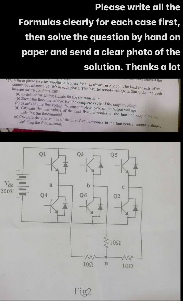
Q4) A three-phase inverter supplies a 3-phase load, as shown in Fig (2). The load consists of star
connected resistance of 1002 in each phase. The inverter supply voltage is 200 V dc, and each
inverter switch conducts 180°.
(a) Sketch the switching signals for the six transistors.
(b) Sketch the line-line voltage for one complete cycle of the output voltage
(c) Sketch the line-line voltage for one complete cycle of the output voltage
(d) Calculate the rms values of the first five harmonics in the line-line output voltage,
including the fundamental.
(e) Calculate the rms values of the first five harmonics in the line-neutral output voltage.
including the fundamental.)
Vac
200V
Q1
Q3
Q5
B
Q6
b
Q2
ww
10Ω
Fig2
3
1092
ww
1092
Expert Solution
This question has been solved!
Explore an expertly crafted, step-by-step solution for a thorough understanding of key concepts.

Step by stepSolved in 2 steps with 4 images

Knowledge Booster

Similar questions
- The IT servers for a medium-sized company need to be protected fromgrid failures (e.g. blackout) and thus is powered through anuninterruptable power supply (UPS) unit. The UPS consists of a 3-phase diode rectifier powering the dc bus, which then splits between a3-phase inverter unit and a battery energy storage system (BESS). UPSparameters are given in Table B2 and a general schematic is shown inFigure B2.a) Assuming that the inverter and BESS pull a combined constant current,IDC, from the dc bus, draw the approximate waveforms over one full accycle for: (i) the three ac line voltages, (ii) the three ac currents, and(iii) the total dc bus voltage.arrow_forwardThe IT servers for a medium-sized company need to be protected from grid failures (e.g. blackout) and thus is powered through an uninterruptable power supply (UPS) unit. The UPS consists of a 3- phase diode rectifier powering the dc bus, which then splits between a 3-phase inverter unit and a battery energy storage system (BESS). UPS parameters are given in Table B2 and a general schematic is shown in Figure B2. Assuming that the inverter and BESS pull a combined constant current, IDC, from the dc bus, draw the approximate waveforms over one full ac cycle for: (i) the three ac line voltages, (ii) the three ac currents, and (iii) the total dc bus voltage. Explain how the single-phase inverter operates and draw an approximate waveform of the load-side ac voltage. Comment on the chosen switching frequency for the inverter. Choose a dc/dc converter topology for the BESS. Draw the converter diagram for your chosen topology and justify each of your design choices. Estimate the battery…arrow_forwardFor an RTD the relationship between resistance and temperature is a. proportional b. no relation c. equal d. inversely proportionalarrow_forward
- Find voltage regulation in typing format please ASAP for the likearrow_forwardPlease show steps and workarrow_forward(b) Design a 20V D.C. power supply using full-wave rectifier(s), a transformer (220Vms, 50HZ) and a 470uF capacitor, supplying a resistor load of Ik2. Draw the circuit diagram • Sketch the output waveform Determine the transformer ratio • Determine the output voltage ripplearrow_forward
- Evaluate the use of analogue and digital electronic devices, in complex systems like a scientific calculator and an amplifier. For the calculator look at the input components such as chips (IC) on a circuit board, switches what do they do. The processor (microprocessor) chip (IC), central processing unit (CPU), what does it do. The output, display screen LCD, what does it do. The power source, batteries, lithium, alkaline. Where would you expect AND, OR, NOT, EXOR gates to be used. What are FULL ADDER/HALF ADDER circuits show the circuits. How is multiplication done. For the amplifier Look at the input, a small voltage/current is applied, uses the power supply to help to increase the input signal, via a transistor/op-amp integrated circuit (IC). Uses, to drive headphones, speakers. Types of amplifiers, Audio frequency, Radio Frequency, video amplifiers etc. Classes of amplifiers such as class A, B, C and AB.arrow_forwardYour family have a small house in the countryside which is not connected to the grid. The place enjoys 3.5 equivalent sun hours. Therefore, you have decided to install an off-grid PV system in the house to supply their electricity. you will be using PV modules with the following specifications: P, We may assume that the combined efficiency of the cables, the charge controller and the battery system is 90% and that of the inverter is 96%. As the house is only used at the weekend, only two days of autonomy will be needed. In this case, batteries with the following specifications will be used: capacity 100 Ah, voltage 12 V, maximum allowed depth of discharge 50%. The daily house electricity requirements are summarized in the Table. = 100 Wp, VMpP =16 V, IMpp = 6.25 A, Voc = 18 V, Isc = 7 A. %3D nom Quantity 10 Time of use (h) Type Power per item (W) 20 Load Light bulb TV DC 1. Calculate the total daily electricity demand in Wh. 2. What is the total power demanded by the DC loads? 3. What…arrow_forwardThree phase Bridge rectifier operated from a 380V, 50Hz source throughout three-phase Y/Y connected transformer with ration 2:1. The load current has continuous character with negligible ripples and average thyristor current of 15A. The circuit inductance per phase is 1.2mH. The rectified voltage due to overlapping angle is 90 % of that voltage when this angle is neglected. 1- How much will the voltage drop be due to circuit inductance * 2- How much will the dc average voltage Vdc(alpha) be. 3- How much will the firing angle be ? 4- The overlapping angle. 5- How much is the percentage change of the output dc power if the thyristors T2, T4 and T6 are replaced by three diodes D2, D4, D6. 6- How much will be the maximum RMS phase current for the mentioned in previous task circuit ( semi-converter). 7- If an additional of 1 mH inductances are added to the existing inductances in the phases , how much will the overlapping angle be. The dc load current is kept constant & the…arrow_forward
- Q4) A three-phase inverter supplies a 3-phase load, as shown in Fig (2). The load consists of star connected resistance of 102 in each phase. The inverter supply voltage is 200 V dc, and each inverter switch conducts 180° (a) Sketch the switching signals for the six transistors. (b) Sketch the line-line voltage for one complete cycle of the output voltage (c) Sketch the phase-line voltage for one complete cycle of the output voltage (d) Calculate the rms values of the first five harmonics in the phase-line output voltage, including the fundamental. (e) Calculate the rms values of the first five harmonics in the line-neutral output voltage, including the fundamental.) Vac 200V Q1 h Q3 Q5 a Q6 Q4 120° conuction 2 102 ww 1052 ww n 102arrow_forwardA single phase half bridge inverter has a resistance of 2.5Ω and input DC voltage of 50V. Calculate the following O/p rms voltage and currentarrow_forwardPlease assist with this question with details on how to do it. Thank you.....arrow_forward
arrow_back_ios
SEE MORE QUESTIONS
arrow_forward_ios
Recommended textbooks for you
- Introductory Circuit Analysis (13th Edition)Electrical EngineeringISBN:9780133923605Author:Robert L. BoylestadPublisher:PEARSON
 Delmar's Standard Textbook Of ElectricityElectrical EngineeringISBN:9781337900348Author:Stephen L. HermanPublisher:Cengage Learning
 Programmable Logic ControllersElectrical EngineeringISBN:9780073373843Author:Frank D. PetruzellaPublisher:McGraw-Hill Education
  Fundamentals of Electric CircuitsElectrical EngineeringISBN:9780078028229Author:Charles K Alexander, Matthew SadikuPublisher:McGraw-Hill Education
 Electric Circuits. (11th Edition)Electrical EngineeringISBN:9780134746968Author:James W. Nilsson, Susan RiedelPublisher:PEARSON
 Engineering ElectromagneticsElectrical EngineeringISBN:9780078028151Author:Hayt, William H. (william Hart), Jr, BUCK, John A.Publisher:Mcgraw-hill Education,
Introductory Circuit Analysis (13th Edition)
Electrical Engineering
ISBN:9780133923605
Author:Robert L. Boylestad
Publisher:PEARSON
Delmar's Standard Textbook Of Electricity
Electrical Engineering
ISBN:9781337900348
Author:Stephen L. Herman
Publisher:Cengage Learning
Programmable Logic Controllers
Electrical Engineering
ISBN:9780073373843
Author:Frank D. Petruzella
Publisher:McGraw-Hill Education
Fundamentals of Electric Circuits
Electrical Engineering
ISBN:9780078028229
Author:Charles K Alexander, Matthew Sadiku
Publisher:McGraw-Hill Education
Electric Circuits. (11th Edition)
Electrical Engineering
ISBN:9780134746968
Author:James W. Nilsson, Susan Riedel
Publisher:PEARSON
Engineering Electromagnetics
Electrical Engineering
ISBN:9780078028151
Author:Hayt, William H. (william Hart), Jr, BUCK, John A.
Publisher:Mcgraw-hill Education,