
Introductory Circuit Analysis (13th Edition)
13th Edition
ISBN: 9780133923605
Author: Robert L. Boylestad
Publisher: PEARSON
expand_more
expand_more
format_list_bulleted
Related questions
Question
Find the mathematical expression for the points 1 and 2 for this pratical AM-DSB/SC modulator
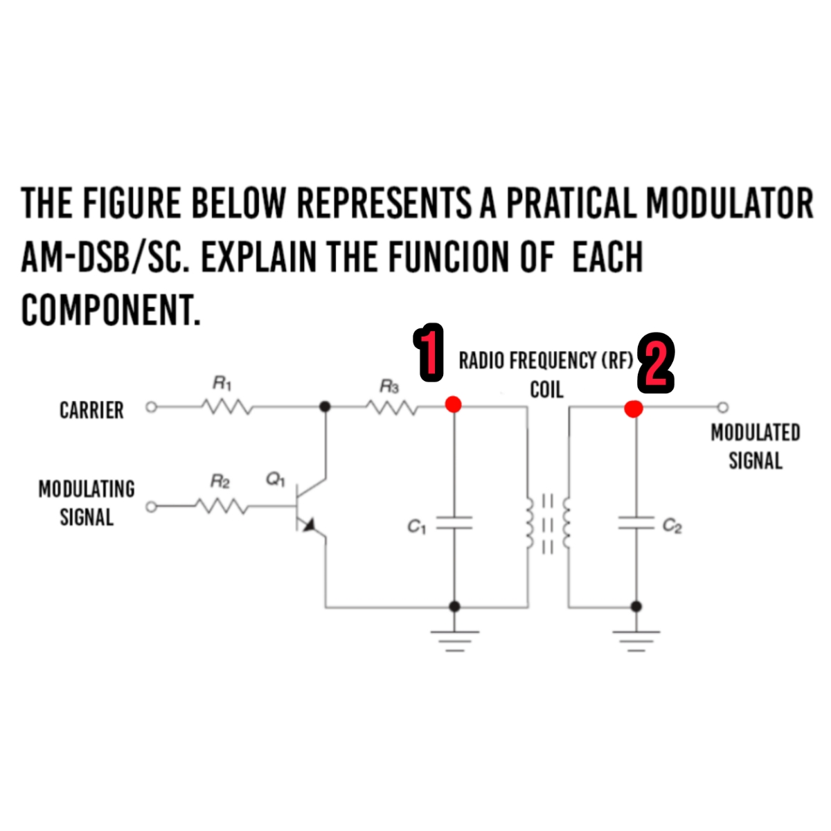

Transcribed Image Text:THE FIGURE BELOW REPRESENTS A PRATICAL MODULATOR
AM-DSB/SC. EXPLAIN THE FUNCION OF EACH
COMPONENT.
1
RADIO FREQUENCY (RF)
R₁
2
R3
COIL
CARRIER
w
R2
Q₁
MODULATING
SIGNAL
5
MODULATED
SIGNAL
S
Expert Solution
This question has been solved!
Explore an expertly crafted, step-by-step solution for a thorough understanding of key concepts.

Step by stepSolved in 2 steps with 1 images

Knowledge Booster

Similar questions
- The circuit is shown below, Vin is the sinusoidal waveform with magnitude 5V and frequency is 100 Hz, R = 1 k, C = 1 uE, the chip is supplied by + 12 V source. a) What is the waveform of Yout? b) Calculate the magnitude of Vo c) If Vin is triangle waveform, what is the output waveform? -Vout , if Vin is triangle waveform with magnitude of 5 V (peak-to-peak value is 10 V) and frequency is 10 kHz, calculate waveform of you and the magnitude of I/?arrow_forwardI need a clear step by step answer please and explanation please on how to obtain the values of Th and Tl and Vlarrow_forwardshow formula and methodarrow_forward
- Sequential Circuits, Thank you in advance for your answer.arrow_forward3arrow_forwardA boost converter is required to have an output voltage of 8 V andsupply a load current of 1 A. The input voltage varies from 2.7 to4.2 V. A control circuit adjusts the duty cycle to keep the outputvoltage constant. If the switching frequency is 200 kHz, determine:i. a value for the inductor such that the variation in inductorcurrent is no more than 40% of the average inductor current forall operating conditions.ii. a value for the capacitor such that the output voltage ripple isno more than 2%.iii. in case the OFF period is reduced by 30% for constantfrequency operation, find the new output voltagearrow_forward
- Transform and draw the equivalent small signal circuit model using ONLY theHYBRID-PI model.arrow_forwardDefine ICBO and ICEO. How are they different? How are they related? Are they typically close in magnitude?arrow_forwardBuck Converter Design Power supplies for telecommunications applications may require high currents at low voltages. Design a buck converter that has an input voltage of 3.3 V and an output voltageof 1.2 V. The output current varies between 4 and 6 A. The output voltage ripple mustnot exceed 2 percent. Specify the inductor value such that the peak-to-peak variation in inductor current does not exceed 40 percent of the average value. Determine the required rms current rating of the inductor and of the capacitor. Determine the maximum equivalentseries resistance of the capacitor.arrow_forward
- Use multi-vibration circuits and create a signal generator that produces a square, triangular, and sinusoidal waveform with a frequency of 1kHz. Show work for theoretical layout. Also, use a switch for each waveform.arrow_forwardIn a Wien bridge oscillator circuit, resistor and capacitor form a series branch and a parallel branch. The value of the resistor is 200 ohm and the value of the capacitor is 10 mF. Determine the frequency of oscillation for the Wien Bridge oscillator circuit.arrow_forwardQuestions: Draw output waveform for the following circuits if sinusoidal signal of 6V peak-to-peak with zero offset is applied at the input. Consider reference voltage VR = +2V R. VR Consider Zener voltage 2.5V Dz * R VR = -3V v,(f) 22arrow_forward
arrow_back_ios
SEE MORE QUESTIONS
arrow_forward_ios
Recommended textbooks for you
- Introductory Circuit Analysis (13th Edition)Electrical EngineeringISBN:9780133923605Author:Robert L. BoylestadPublisher:PEARSON
 Delmar's Standard Textbook Of ElectricityElectrical EngineeringISBN:9781337900348Author:Stephen L. HermanPublisher:Cengage Learning
 Programmable Logic ControllersElectrical EngineeringISBN:9780073373843Author:Frank D. PetruzellaPublisher:McGraw-Hill Education
  Fundamentals of Electric CircuitsElectrical EngineeringISBN:9780078028229Author:Charles K Alexander, Matthew SadikuPublisher:McGraw-Hill Education
 Electric Circuits. (11th Edition)Electrical EngineeringISBN:9780134746968Author:James W. Nilsson, Susan RiedelPublisher:PEARSON
 Engineering ElectromagneticsElectrical EngineeringISBN:9780078028151Author:Hayt, William H. (william Hart), Jr, BUCK, John A.Publisher:Mcgraw-hill Education,
Introductory Circuit Analysis (13th Edition)
Electrical Engineering
ISBN:9780133923605
Author:Robert L. Boylestad
Publisher:PEARSON
Delmar's Standard Textbook Of Electricity
Electrical Engineering
ISBN:9781337900348
Author:Stephen L. Herman
Publisher:Cengage Learning
Programmable Logic Controllers
Electrical Engineering
ISBN:9780073373843
Author:Frank D. Petruzella
Publisher:McGraw-Hill Education
Fundamentals of Electric Circuits
Electrical Engineering
ISBN:9780078028229
Author:Charles K Alexander, Matthew Sadiku
Publisher:McGraw-Hill Education
Electric Circuits. (11th Edition)
Electrical Engineering
ISBN:9780134746968
Author:James W. Nilsson, Susan Riedel
Publisher:PEARSON
Engineering Electromagnetics
Electrical Engineering
ISBN:9780078028151
Author:Hayt, William H. (william Hart), Jr, BUCK, John A.
Publisher:Mcgraw-hill Education,