
Concept explainers
Videos
9.29 and 9.30 Determine the reaction at the roller support and the deflection at point C.
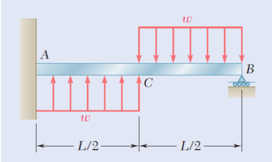
Fig. P9.30
Find the reaction at the roller support and the deflection at point C of the beam.
Answer to Problem 30P
The reaction at the roller support B is
The deflection at point C of the beam is
Explanation of Solution
Consider a section at a distance x from left end A of the section AC.
Show the free-body diagram of the section AC as in Figure 1.
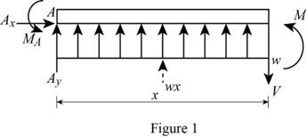
Determine the moment at the section by taking moment about the section.
Write the second order differential equation as follows;
Here, the moment at the corresponding section is
Substitute
Integrate the equation with respect to x;
Integrate the Equation (2) with respect to x.
Show the free-body diagram of the section BC as in Figure 2.
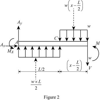
Determine the moment at the section by taking moment about the section.
Substitute
Integrate the equation with respect to x;
Integrate the Equation (4) with respect to x.
Boundary condition 1:
At the point A;
Substitute 0 for x and 0 for y in Equation (3).
Boundary condition 2:
At the point A;
Substitute 0 for x and 0 for
Boundary condition 3:
At the point C;
Equate Equation (2) and (4).
Substitute
Boundary condition 4:
At the point C;
Equate Equation (3) and (5).
Substitute
Boundary condition 5:
At the point B;
Substitute L for x, 0 for y,
Show the free-body diagram of the beam AB as in Figure 3.
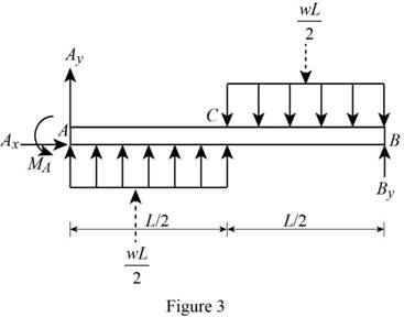
Resolve the vertical component of forces as follows;
Take moment about the point A as follows;
Substitute
Therefore, the reaction at the roller support B is
Substitute
Substitute
At point C;
Substitute
Therefore, the deflection at point C of the beam is
Want to see more full solutions like this?
Chapter 9 Solutions
EBK MECHANICS OF MATERIALS


- Fig. P9.78 E 9.79 and 9.80 For the uniform beam shown, determine (a) the reaction at A, (b) the reaction at B. ***** A Fig. P9.80 -L/2- Answer (a) 7 wL/128 1. (b)57 wL/128 1:9wL2/128. C -L/2- Barrow_forwardb. Determine the deflection of the beam at midpoint for the beam loading system shown in the figure given below : Take : E = 200 GN/m? and I = 83 x 106 m4. 20 N 30 N 10 N/m 10 m 5 m 10 m Fig. 10.arrow_forward9.11 For the cantilever beam shown, determine the slope and deflection at (a) point B, (b) point C. Use E = 29 × 106 psi. w = 600 lb/ft A -6 ft- Fig. P9.11 B 1200 lb --+-3A- H W 8x 15arrow_forward
- P = 150 kN PROBLEM 9.13 For the beam and loading shown, determine the deflection at point C. Use E = 200 GPa. W360 x 44 a = 1.5 m -L= 4.5 m- [x = 0, y = 0] [x = a, y = y] [x = L. y = 0] dy a, dx dy dx Yc = 9.2 mm,arrow_forwardPROBLEM 9.14 For the beam and loading shown, knowing that a=2 m, w= 50 kN/m. and E = 200 GPa, determine (a) the slope at support A, (b) the deflection at point C. W310 x 38.7 L = 6 m- e = 8.18 x 10 rad Yc =11.78 mmarrow_forwardQ.4) Determine the deflection of the beam at point C. 7.arrow_forward
- 4. For the truss structure shown, determine the vertical deflection at B by using the Principle of Virtual Work. The area of each member is 10 sq. in. E = 30x10 psi. 50 kips B 15 A 15 D C 20¹ 20¹arrow_forward6.36 Using Castigliano's method on the wire form shown determine the vertical deflection of point A considering bending only. The rigidity of the cross sec- tion is El. R Problem 6.36 Barrow_forwardA beam ABCD, 6 m long, is simply-supported at the right-hand end D and at a point B 1 m from the left hand end A. It carries a vertical load of 10 kN at A, a second concentrated load of 20 kN at C, 3 m from D, and a uniformly distributed load of 10 kN/m between C and D. Determine the position and magnitude of the maximum deflection if E = 208 GN/m2 and I = 35 x10^-6 m4.arrow_forward
- 3.2 kN 300 mm B 75 mm A 9.77 The steel bars BE and AD each have a 6 × 18-mm cross section. Knowing that E = 200 GPa, determine the deflections of points A, B, and C of the rigid bar ABC. 400 mm-+400 mm Fig. P9.77arrow_forwardPROBLEM 9.9 Knowing that beam AB is a W130× 23.8 rolled shape and that L P=50 kN, L=1.25 m, and E = 200 GPa, determine (a) the slope at A, (b) the deflection at C. L/2 L/2 [x=0, y=0] [x = L, y=0] L dy 2' dx e = 2.77x10³ rad Yc = 1.156 mm.arrow_forwardA 7/8-in.-diameter rod BC is attached to the lever AB and to the fixed support at C. Lever AB has a uniform cross section 38 in. thick and 1 in. deep. For the loading shown, determine the deflection of point A. Use E=29 *106 psi and G=11.2 *106 psi.arrow_forward
 Elements Of ElectromagneticsMechanical EngineeringISBN:9780190698614Author:Sadiku, Matthew N. O.Publisher:Oxford University Press
 Mechanics of Materials (10th Edition)Mechanical EngineeringISBN:9780134319650Author:Russell C. HibbelerPublisher:PEARSON
 Thermodynamics: An Engineering ApproachMechanical EngineeringISBN:9781259822674Author:Yunus A. Cengel Dr., Michael A. BolesPublisher:McGraw-Hill Education
 Control Systems EngineeringMechanical EngineeringISBN:9781118170519Author:Norman S. NisePublisher:WILEY
 Mechanics of Materials (MindTap Course List)Mechanical EngineeringISBN:9781337093347Author:Barry J. Goodno, James M. GerePublisher:Cengage Learning
 Engineering Mechanics: StaticsMechanical EngineeringISBN:9781118807330Author:James L. Meriam, L. G. Kraige, J. N. BoltonPublisher:WILEY