
Concept explainers
Videos
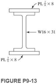
Use both LRFD and ASD methods for these beams for which full lateral bracing of the compression flange is provided.
9-13. The section shown in Fig. P9-13 has two
Want to see the full answer?
Check out a sample textbook solution
Chapter 9 Solutions
Structural Steel Design (6th Edition)


- 0O REDMI NOTE 8 PRO O AI QUAD CAMERA Q - 4. For the given truss structure below; BY USING THE METHOD of SECTIONS; determine the internal forces of the elements BD, CD & CE. Also determine whether these forces are TENSILE or COMPRESSIVE. 3 in 3 m -4 m -4 m -4 m- 1.75 kN 2KN 1.5 kN 2kN I kN 9.75 kN G 6 m 6 m 6m 6 marrow_forwardb Irom Fig. 9-10 in the text. 9-17. Select the lightest satisfactory W shape section if Fy provided at the ends only. Determine C,. (Ans. W24 × 117 LRFD and ASD) 50 ksi. Lateral bracing is PL = 40 k PL = 40 k D = 1 k/ft U PES %3D 10 ft 10 ft 10 ft FIGURE P9-17 9-18. Repeat Prob. 9-17 if lateral bracing is provided at the concentrated loads as well as at the ends of the span. Determine C,.arrow_forwardA plate girder must be designed for the conditions shown in Figure P10.7-4. The given loads are factored, and the uniformly distributed load includes a conservative estimate of the girder weight. Lateral support is provided at the ands and at the load points. Use LRFD for that following: a. Select the, flange and web dimensions so that intermediate stiffeners will he required. Use Fy=50 ksi and a total depth of 50 inches. Bearing stiffeners will be used at the ends and at the load points, but do not proportion them. b. Determine the locations of the intermediate stiffeners, but do not proportion them.arrow_forward
- The steelwork framing plan for a floor system shows decks as D1-D12, beams and girders as M1- M20 and columns as C1-C9. The unit load on the system is 75-psf dead and 45-psf live. What is the total load going into column C2? C3 C1 C2 I. M1 M2 D3 M8 M3 M4 M5 M6 D1 D2 D4 36' M7 D5 C5 C6 C4 M9 M10 D6 M16 M17 M18 M19 M11 M12 D7 D10 D11 D12 40' M13 D8 M14 D9 I. C9 C7 C8 M20 M15 24' 16'arrow_forwardA plate girder cross section consists of two flanges, 11⁄2 inchesx 15 inches, and a 5⁄16-inch 3 66-inch web. A572 Grade 50 steel is used. The span length is 55 feet, the service live load is 2.0 kips/ft, and the dead load is 0.225 kips/ft, including the weight of the girder. Bearing stiffeners are placed at the ends, and intermediate stiffeners are placed at 69-20 and 12,-9,, from each end. Does this girder have enough shear strength? a. Use LRFD. b. Use ASDarrow_forwardAn 80-foot long plate girder (see below) is fabricated from a ½-inch x 78-inch web and two 3inch x 22-inch flanges. Continuous lateral support is provided. The steel is A992. The loading consists of a uniform service dead load of 1.0 kip/ft (including the self-weight), a uniform service live load of 2.0 kips/ft, and a concentrated service live load of 500 kips at midspan. Stiffeners are placed at each end and at 4 feet, 16 feet, and 28 feet from each end. Once stiffener is placed at midspan. Determine whether the flexural strength is adequate using LRFD.arrow_forward
- Problem: Design all tension members of the truss shown. Use LRFD Principles. 1.5 kips (L) 1 kips (W) 3 kips (L) 1 kips (W) Live Load (L) + Wind Load (W) 3 kips (L) 1 kips (W) 3 kips (L) 1 kips (W) 3 kips (L) 1 kips (W) 8 @ 1.0 m 3 kips (L) 3 kips (L) 3 kips (L) 3 kips (L) 3.0 marrow_forwardFor the Integrated Project (office building), design the Floor Girders in the gravity-only system, assuming that the top flange is fully restrained with the floor diaphragm. 1. Use Table 3-2 from the Steel Manual to select the most economical compact W-shape section. Demands: Stories 1 and 2 Edge: 114.4 k.ft From Table 3-2, use W12x50 D/C = should be less than 0.95: D/C = Stories 1 and 2 Interior: 226.4 k.ft Use W12x50: D/C = Roof Edge: 33.3 k.ft Use W12x40: D/C = Roof Interior: 58.4 k.ft Use W12x40: D/C =arrow_forwardQ4: Calculate the forces induced in members KL, CL, and CB by the 20-ton load on the cantilever truss. M K 26 16' G F D B A -6 panels at 12' 20 tonsarrow_forward
- 2. Find the force acting in Bar AC, CE, DE, DF & FH of the Truss as shown in the below figure. B F E 1000 ib 1000 b 1000 b A -12 12 -12- -12 RA RBarrow_forwardThe floor structural system shown in Fig 1 comprise W-section steel beams and girders supporting a 5-inch thick concrete slab which provides full restraint to the flanges of the beams. The density of concrete is 150 lbs./ft'. and the uniformly distributed live load L- 50 lbs/ft². L-22 B. Girder G1: - B [za] 12' GI GI 12 + [ial FIG. 1-Steel Floor Beam a) Strength - Bending and Shear -I 1) Produce a sketch of the floor plan showing the tributary load distribution areas for the beams and girders [za]arrow_forwardPLATE #3 PROBLEM: A built up section of A992 steel is made from plates fully welded together. The flanges consist of PL16x380 and PL12x500 for the web. Check the beam for flexure. Total load Deflection is limited to L/240. Cite all applicable specifications you used to solve the problem from NSCP 2015. 1. For full lateral support 2. For Lateral bracing at supports and midspan of AB. WD 3. For lateral bracing at supports only, what maximum w and w₁ can the beam carry for WL A WD = 26 kN/m_Includes self wt. WL = 40 kN/m B 10m ee m 2m PL16x380 PL12x500 X = 1.5.arrow_forward
 Steel Design (Activate Learning with these NEW ti...Civil EngineeringISBN:9781337094740Author:Segui, William T.Publisher:Cengage Learning