
(a)
Interpretation:
The circulation rate of refrigerant for the given system is to be calculated.
Concept introduction:
Below shown diagram represents vapor-compression refrigeration cycle on a
The line
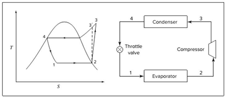
The equations used to calculate the heat absorbed in evaporator and the heat rejected in condenser are:
The work of compression is:
The coefficient of performance is:
The rate of circulation of refrigerant,
For Carnot refrigeration cycle, highest possible value of
(b)
Interpretation:
The reduction in the circulation rate is to be calculated if throttle valve is replaced by a turbine where the refrigerant expands isentropically.
Concept introduction:
Below shown diagram represents vapor-compression refrigeration cycle on a
The line

The equations used to calculate the heat absorbed in evaporator and the heat rejected in condenser are:
The work of compression is:
The coefficient of performance is:
The rate of circulation of refrigerant,
For Carnot refrigeration cycle, highest possible value of
(c)
Interpretation:
If the cycle of (a) is modified, from the condenser if liquid enters the exchanger at
Concept introduction:
Below shown diagram represents vapor-compression refrigeration cycle on a
The line

The equations used to calculate the heat absorbed in evaporator and the heat rejected in condenser are:
The work of compression is:
The coefficient of performance is:
The rate of circulation of refrigerant,
For Carnot refrigeration cycle, highest possible value of
(d)
Interpretation:
The coefficient of performance for all the parts (a), (b), and (c) are to be calculated for isentropic compression.
Concept introduction:
Below shown diagram represents vapor-compression refrigeration cycle on a
The line

The equations used to calculate the heat absorbed in evaporator and the heat rejected in condenser are:
The work of compression is:
The coefficient of performance is:
The rate of circulation of refrigerant,
For Carnot refrigeration cycle, highest possible value of
Want to see the full answer?
Check out a sample textbook solution
Chapter 9 Solutions
Introduction to Chemical Engineering Thermodynamics

 Introduction to Chemical Engineering Thermodynami...Chemical EngineeringISBN:9781259696527Author:J.M. Smith Termodinamica en ingenieria quimica, Hendrick C Van Ness, Michael Abbott, Mark SwihartPublisher:McGraw-Hill Education
 Elementary Principles of Chemical Processes, Bind...Chemical EngineeringISBN:9781118431221Author:Richard M. Felder, Ronald W. Rousseau, Lisa G. BullardPublisher:WILEY
 Elements of Chemical Reaction Engineering (5th Ed...Chemical EngineeringISBN:9780133887518Author:H. Scott FoglerPublisher:Prentice Hall
 Industrial Plastics: Theory and ApplicationsChemical EngineeringISBN:9781285061238Author:Lokensgard, ErikPublisher:Delmar Cengage Learning
 Unit Operations of Chemical EngineeringChemical EngineeringISBN:9780072848236Author:Warren McCabe, Julian C. Smith, Peter HarriottPublisher:McGraw-Hill Companies, The