
Electric Motor Control
10th Edition
ISBN: 9781133702818
Author: Herman
Publisher: CENGAGE L
expand_more
expand_more
format_list_bulleted
Concept explainers
Videos
Textbook Question
Chapter 9, Problem 8SQ
Connect the following components in Figure 9–18:
- a. Start push button to the timer coil
- b. Load 1 to NCTC
- c. Load 2 to NOTO
- d. Show proper symbols
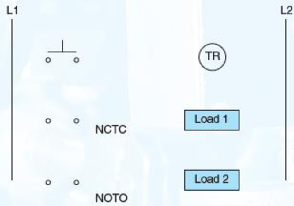
FIG. 9–18
Expert Solution & Answer
Want to see the full answer?
Check out a sample textbook solution
Students have asked these similar questions
For the circuit shown in Fig. 2.18, he =1.1 K2, hfe =50. Find Avf, Rif and Rof.
{ Ans: -3.2; 1935; X2807.
Ans:-3-2;193;728. Vcc
Rs=10kQ
RF = 40kQ
Re=4KQ
-ov
Vs
For the system shown in figure below, the per unit values of different quantities are
E-1.2, V 1, X X2-0.4. Xa-0.2
Determine whether the system is stable for a sustained fault.
The fault is cleared at 8-60°. Is the system stable? If so find the maximum
rotor swing.
Find the critical clearing angle.
E25
G
X'd
08
CB
X2
F
CB
V28
Infinite
bus
17 For the circuit shown in Fig. 2.20, the transistors are identical and have the following
parameters: hfe = 50, hie 1.1K, hre = 0, and hoe = 0. Calculate Auf, Rif and Rof.
25 V
{Ans #45.4; 112 KM; 129
150k
47k
www
www
+11
www
10k
6
4.7k
50μF
Rif
R₂1000
w
4.7k
47k
Vo
Q2
33k
4.7k
ww
50µF
5μF
4.7k
1
R₁
Rof
Chapter 9 Solutions
Electric Motor Control
Ch. 9 - List several applications for a motor-driven...Ch. 9 - Which timer is the most commonly used in...Ch. 9 - How is a pneumatic timer adjusted?Ch. 9 - List six factors to be considered when selecting a...Ch. 9 - List several additional factors that will affect...Ch. 9 - Prob. 6SQCh. 9 - Connect these components in Figure 917: a. The...Ch. 9 - Connect the following components in Figure 918: a....
Knowledge Booster


Learn more about
Need a deep-dive on the concept behind this application? Look no further. Learn more about this topic, electrical-engineering and related others by exploring similar questions and additional content below.Similar questions
- For the circuit shown in Fig. 2.18, he =1.1 K2, hfe =50. Find Avf, Rif and Rof. { Ans: -3.2; 1935; X2807. Ans:-3-2;193;728. Vcc Rs=10kQ RF = 40kQ Re=4KQ -ov Vs Fig. 2.18 Circuit for Q5.arrow_forwardThe circuit of Fig. 2.16 is to have Af=-1mA/V, D=1+ BA = 50, a voltage gain of -4, Rs =1KQ, and hfe = 150. Find RL, Re, Rif and Rof.. Vcc www RL OV Ans: 4 kor; 98053150 KS;∞. { An Re Fig. 2.16 Circuit for Q3.arrow_forwardDuring the lab you will design and measure a differential amplifier, made with an opamp. inside generator R5 ww 500 V1 0.1Vpk 1kHz 0° R6 w 50Ω R1 ww 10ΚΩ VCC C1 balanced wire R3 w 15.0V signal+ 100nF U1A TL082CP ground 2 signal- R4 w C2 Question5: Calculate R3 and R4 for a 20dB. 100nF VEE -15.0V R2 ww 10ΚΩarrow_forward
- not use ai pleasearrow_forward3. Consider the system described by the transfer function Gp(s) polynomial controller to satisfy the below specifications: 1) The settling time is t = 1 second, 2) 0.1% peak overshoot, 3) and zero steady-state error for a ramp input. The sampling period is T = 0.01 second. 1 = Design a discrete-time s(s+5)*arrow_forwardProblem 2 Does there exist a value a that makes the two systems S₁ and S₂ equal? If so, what is this value ? If not, explain why. S₁ x[n] x[n] D D -2 → host 回洄 S with h[m] " 999. усиз -1012345 harrow_forward
- please not use any aiarrow_forwardProblem 2 Does there exist a value a that makes the two systems S₁ and S₂ equal? If so, what is this value ? If not, explain why. S₁ x[n] x[n] D D -2 → host 回洄 S with h[m] " 999. усиз -1012345 harrow_forwardSolve only no 8, Don't use chatgpt or any , only expertarrow_forward
- I need help in creating a matlab code to find the currents USING MARTIXS AND INVERSE to find the currentarrow_forwardQuestion 2 A transistor is used as a switch and the waveforms are shown in Figure 2. The parameters are Vcc = 225 V, VBE(sat) = 3 V, IB = 8 A, VCE(sat) = 2 V, Ics = 90 A, td = 0.5 µs, tr = 1 µs, ts = 3 µs, tƒ = 2 μs, and f 10 kHz. The duty cycle is k 50%. The collector- emitter leakage current is ICEO = 2 mA. Determine the power loss due to the collector current: = = = (a) during turn-on ton = td + tr VCE Vcc (b) during conduction period tn V CE(sat) 0 toff" ton Ics 0.9 Ics (c) during turn-off toff = ts + tf (d) during off-time tot (e) the total average power losses PT ICEO 0 IBS 0 Figure 2 V BE(sat) 0 主 * td tr In Is If to iB VBE T= 1/fsarrow_forwardQuestion 1: The beta (B) of the bipolar transistor shown in Figure 1 varies from 12 to 60. The load resistance is Rc = 5. The dc supply voltage is VCC = 40 V and the input voltage to the base circuit is VB = 5 V. If VCE(sat) = 1.2 V, VBE(sat) = 1.6 V, and RB = 0.8 2, calculate: (a) the overdrive factor ODF. (b) the forced ẞ (c) the power loss in the transistor PT. IB VB RB + V BE RC Vcc' Ic + IE Figure 1 VCEarrow_forward
arrow_back_ios
SEE MORE QUESTIONS
arrow_forward_ios
Recommended textbooks for you
 Electricity for Refrigeration, Heating, and Air C...Mechanical EngineeringISBN:9781337399128Author:Russell E. SmithPublisher:Cengage Learning
Electricity for Refrigeration, Heating, and Air C...
Mechanical Engineering
ISBN:9781337399128
Author:Russell E. Smith
Publisher:Cengage Learning
Latches and Flip-Flops 1 - The SR Latch; Author: Computer Science;https://www.youtube.com/watch?v=-aQH0ybMd3U;License: Standard Youtube License