
Loose Leaf for Engineering Circuit Analysis Format: Loose-leaf
9th Edition
ISBN: 9781259989452
Author: Hayt
Publisher: Mcgraw Hill Publishers
expand_more
expand_more
format_list_bulleted
Videos
Textbook Question
Chapter 9, Problem 49E
Obtain an expression for i1 as labeled in Fig. 9.51 which is valid for all t > 0.
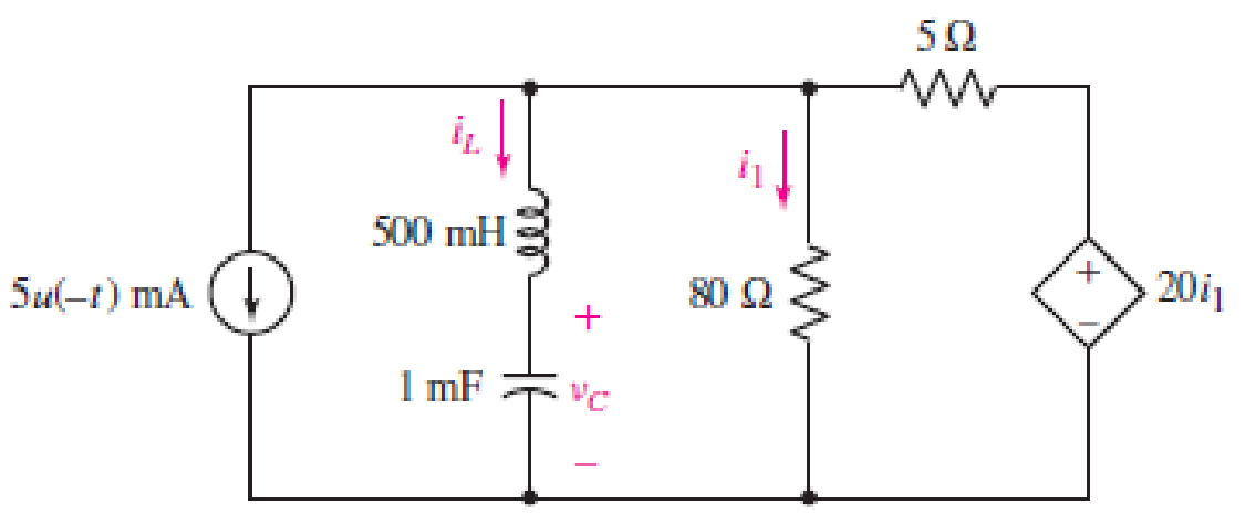
■ FIGURE 9.51
Expert Solution & Answer
Want to see the full answer?
Check out a sample textbook solution
Students have asked these similar questions
3 An function get) Can be SPit unambiguousiy into an elen
Pait and on dd Pait, as Shown by
git) = 9e lt) +Jolt)
The elvlen Part is defined by
gelt) =(9(t) + 9lti)
The odd Paft is defined by
I,lt) =(9(t) - 9l-t)
a) Evaluate the even and odd Pafts of a fectangular Pulse
defined by
gu)-A fed (특늘)
b) what afe the FT of the Se two Palts of the Pulse?
Write a PYTHON Script to find y from the below equations depending on your entry.
tan(4)- cos (0)
sin (0) + cos () :TSos2n , 2n 30S3n
sin (0) + cos ()
sinh(0)+tanh(o²) : Elsewhere
:3n soS 4n, 4n S0S 6n
Example 8: For the system x -+-
of the following statement about the system is true?
(A) Controllable and stable
(B) Uncontrollable and stable
(C) Controllable and unstable
(D) Uncontrollable and unstable
Solution: (D)
#, which
Chapter 9 Solutions
Loose Leaf for Engineering Circuit Analysis Format: Loose-leaf
Ch. 9.1 - A parallel RLC circuit contains a 100 2 resistor...Ch. 9.2 - After being open for a long time, the switch in...Ch. 9.2 - Prob. 3PCh. 9.2 - Prob. 4PCh. 9.3 - (a) Choose R1 in the circuit of Fig. 9.14 so that...Ch. 9.4 - Prob. 6PCh. 9.5 - Prob. 7PCh. 9.5 - Prob. 8PCh. 9.6 - Let is = 10u(t) 20u(t) A in Fig. 9.31. Find (a)...Ch. 9.6 - Let vs = 10 + 20u(t) V in the circuit of Fig....
Ch. 9.7 - Alter the capacitor value and voltage source in...Ch. 9 - For a certain source-free parallel RLC circuit, R...Ch. 9 - Element values of 10 mF and 2 nH are employed in...Ch. 9 - If a parallel RLC circuit is constructed from...Ch. 9 - Prob. 4ECh. 9 - You go to construct the circuit in Exercise 1,...Ch. 9 - A parallel RLC circuit has inductance 2 mH and...Ch. 9 - Prob. 7ECh. 9 - A parallel RLC circuit has R = 1 k, L = 50 mH. and...Ch. 9 - Prob. 9ECh. 9 - Prob. 10ECh. 9 - The current flowing through a 5 resistor in a...Ch. 9 - For the circuit of Fig.9.40, obtain an expression...Ch. 9 - Consider the circuit depicted in Fig. 9.40. (a)...Ch. 9 - With regard to the circuit represented in Fig....Ch. 9 - (a) Assuming the passive sign convention, obtain...Ch. 9 - With regard to the circuit presented in Fig. 9.42,...Ch. 9 - Obtain expressions for the current i(t) and...Ch. 9 - FIGURE 9.43 Replace the 14 resistor in the...Ch. 9 - Design a complete source-free parallel RLC circuit...Ch. 9 - For the circuit represented by Fig. 9.44, the two...Ch. 9 - Prob. 21ECh. 9 - Prob. 22ECh. 9 - A critically damped parallel RLC circuit is...Ch. 9 - A source-free parallel RLC circuit has an initial...Ch. 9 - A critically damped parallel RLC circuit is...Ch. 9 - For the circuit of Fig. 9.45, is(t) = 30u(t) mA....Ch. 9 - Prob. 27ECh. 9 - The circuit of Fig. 9.44 is rebuilt such that the...Ch. 9 - Prob. 29ECh. 9 - Prob. 30ECh. 9 - The source-free circuit depicted in Fig. 9.1 is...Ch. 9 - (a) Graph the current i for the circuit described...Ch. 9 - Analyze the circuit described in Exercise 31 to...Ch. 9 - A source-free parallel RLC circuit has capacitance...Ch. 9 - Prob. 35ECh. 9 - Obtain an expression for vL(t), t 0, for the...Ch. 9 - For the circuit of Fig. 9.47, determine (a) the...Ch. 9 - (a) Design a parallel RLC circuit that provides a...Ch. 9 - The circuit depicted in Fig. 9.48 is just barely...Ch. 9 - When constructing the circuit of Fig. 9.48, you...Ch. 9 - The circuit of Fig. 9.22a is constructed with a...Ch. 9 - Prob. 42ECh. 9 - Prob. 43ECh. 9 - The simple three-element series RLC circuit of...Ch. 9 - Prob. 45ECh. 9 - Prob. 46ECh. 9 - Prob. 47ECh. 9 - With reference to the series RLC circuit of Fig....Ch. 9 - Obtain an expression for i1 as labeled in Fig....Ch. 9 - The circuit in Fig. 9.52 has the switch in...Ch. 9 - For the circuit in Fig. 9.52, determine the value...Ch. 9 - In the series circuit of Fig. 9.53, set R = 1 ....Ch. 9 - Evaluate the derivative of each current and...Ch. 9 - Consider the circuit depicted in Fig. 9.55. If...Ch. 9 - Prob. 55ECh. 9 - In the circuit shown in Fig. 9.56, (a) obtain an...Ch. 9 - Prob. 57ECh. 9 - For the circuit represented in Fig. 9.57, (a)...Ch. 9 - FIGURE 9.57 Replace the 1 resistor in Fig. 9.57...Ch. 9 - A circuit has an inductive load of 2 H, a...Ch. 9 - (a) Adjust the value of the 3 resistor in the...Ch. 9 - Determine expressions for vC(t) and iL(t) in Fig....Ch. 9 - The capacitor in the LC circuit in Fig. 9.60 has...Ch. 9 - Suppose that the switch in the circuit in Fig....Ch. 9 - The capacitor in the circuit of Fig. 9.63 is set...Ch. 9 - The physical behavior of automotive suspension...Ch. 9 - A lossless LC circuit can be used to provide...
Knowledge Booster


Learn more about
Need a deep-dive on the concept behind this application? Look no further. Learn more about this topic, electrical-engineering and related others by exploring similar questions and additional content below.Similar questions
- Q1) B A continuous state-space representation of a system is N-00-A- y = [1 0 [x²] Find the zero order hold discrete-time equivalent of this system.arrow_forwardPhotos - 265121502 2337735863035096_3568501418110557974_n.png 106% A See all photos + Add to 女 & Edit & Create v 12 Share ... Problem #2: Assume that the circuit has been connected for a very long time. (Note: x = 2 (a) As time approaches infinity, what will happen to the capacitor and inductor? (b) From your answer in (a), draw the equivalent circuit (label appropriately) (c) From your circuit in (b), determine the "steady-state" or "final" values of vc, ic , iL and v. 10 A 4 kΩ 5 kN ļic 3 µF 1 kN 2 kN 4 nH Maximum size for new files: 10Marrow_forwardsolve for the dc quantities, VB(Q1), and VB(Q2)arrow_forward
- Please help me understand how to solve this problem, I want to learn how to do it myself or a different variation of these problems. I must learn the steps to approach and solve the problem. Clear writing, please.arrow_forwardSolve for Vo using MILLMAN'S THEOREM Note: DO NOT ROUND OFFUNTIL THE FINAL ANSWER IS OBTAINED. THANKYOU!!arrow_forwardA DT system is described by the difference equationy(n)-3/5y(n-1) + 2/25 y(n-2) = x(n-1) + 1/2x(n-2) Find the poles and zeroes and check whether the system is causal andstable, giving reason for your answerarrow_forward
- RIS) 415+3) K.s Yis) 52+25+64 St2 Draw the root locus of the system given in the figure (K>0). please solve it fast! i will give you thumb up!!!!arrow_forwardLINEAR SYSTEMS SIGNALS AND CLASSIFICATIONS OF SIGNALS ** Show solution stepsarrow_forwardFor the system shown in Figure 1 find the range of values of k for which the system is stable by using the Routh - Hurwitz criterion. Assume that the para. c and d' are positive R(s) Y( 3k S H 2a s+d: H s+b S+Carrow_forward
- The natural response is the behavior of a circuit for a long time when an external excitation is applied. True Falsearrow_forward1. The following system in state space represents the forward path of a unityfeedback system. Use the Routh-Hurwitz criterion to determine if the closed-loop system is stable. 1 -BAD-0- 1 2 x+ T₁ -5-4 y=[101]xarrow_forward2G zain IQ P 2_53098670157... -> Homework 02: a) Write the mathematical expressions for vr, VR1, and i, after the switch is thrown into position 1. b) Find the values of vc, Vr1, and iç when the switch is moved to position 2 at t = 50 ms c) Write the mathematical expressions for v., vR2, and ir after the switch is moved to position 3 at t = 80 ms. a) Plot the waveforms of ve and ic for the time period extending from 0 to 300 ms + vc - C R1 3 kΩ 10μF '3 2 30 V R, 4 ΚΩ ONarrow_forward
arrow_back_ios
SEE MORE QUESTIONS
arrow_forward_ios
Recommended textbooks for you
 Introductory Circuit Analysis (13th Edition)Electrical EngineeringISBN:9780133923605Author:Robert L. BoylestadPublisher:PEARSON
 Delmar's Standard Textbook Of ElectricityElectrical EngineeringISBN:9781337900348Author:Stephen L. HermanPublisher:Cengage Learning
 Programmable Logic ControllersElectrical EngineeringISBN:9780073373843Author:Frank D. PetruzellaPublisher:McGraw-Hill Education
 Fundamentals of Electric CircuitsElectrical EngineeringISBN:9780078028229Author:Charles K Alexander, Matthew SadikuPublisher:McGraw-Hill Education
 Electric Circuits. (11th Edition)Electrical EngineeringISBN:9780134746968Author:James W. Nilsson, Susan RiedelPublisher:PEARSON
 Engineering ElectromagneticsElectrical EngineeringISBN:9780078028151Author:Hayt, William H. (william Hart), Jr, BUCK, John A.Publisher:Mcgraw-hill Education,
Introductory Circuit Analysis (13th Edition)
Electrical Engineering
ISBN:9780133923605
Author:Robert L. Boylestad
Publisher:PEARSON
Delmar's Standard Textbook Of Electricity
Electrical Engineering
ISBN:9781337900348
Author:Stephen L. Herman
Publisher:Cengage Learning
Programmable Logic Controllers
Electrical Engineering
ISBN:9780073373843
Author:Frank D. Petruzella
Publisher:McGraw-Hill Education
Fundamentals of Electric Circuits
Electrical Engineering
ISBN:9780078028229
Author:Charles K Alexander, Matthew Sadiku
Publisher:McGraw-Hill Education
Electric Circuits. (11th Edition)
Electrical Engineering
ISBN:9780134746968
Author:James W. Nilsson, Susan Riedel
Publisher:PEARSON
Engineering Electromagnetics
Electrical Engineering
ISBN:9780078028151
Author:Hayt, William H. (william Hart), Jr, BUCK, John A.
Publisher:Mcgraw-hill Education,
Routh Hurwitz Stability Criterion Basic Worked Example; Author: The Complete Guide to Everything;https://www.youtube.com/watch?v=CzzsR5FT-8U;License: Standard Youtube License