
Videos
Using Fig. 9.43, design a problem to help other students better understand impedance.
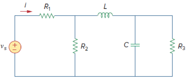
Figure 9.43
Design a problem to make better understand about the impedance using Figure 9.43.
Explanation of Solution
Problem design:
Determine the value of current
Formula used:
Write the expression to convert the time domain expression into phasor domain.
Here,
A is the magnitude,
t is the time, and
Write the expression to calculate the phasor current.
Here,
Write the expression to calculate the impedance of the passive elements resistor, inductor and capacitor.
Here,
Calculation:
The Figure 9.43 is redrawn as Figure 1 by assuming the values for the passive elements.
Given voltage equation is,
Here, angular frequency
Use the equation (1) to express the above equation in phasor form.
Substitute
Substitute
Substitute
Substitute
Substitute
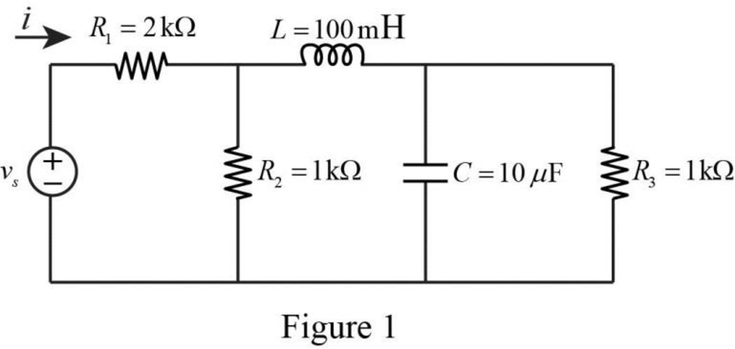
The Figure 1 is redrawn as impedance circuit in the following Figure 2.
Refer to Figure 2, the impedances
Write the expression to calculate the equivalent capacitance 1 for the parallel connected impedances
Here,
Substitute
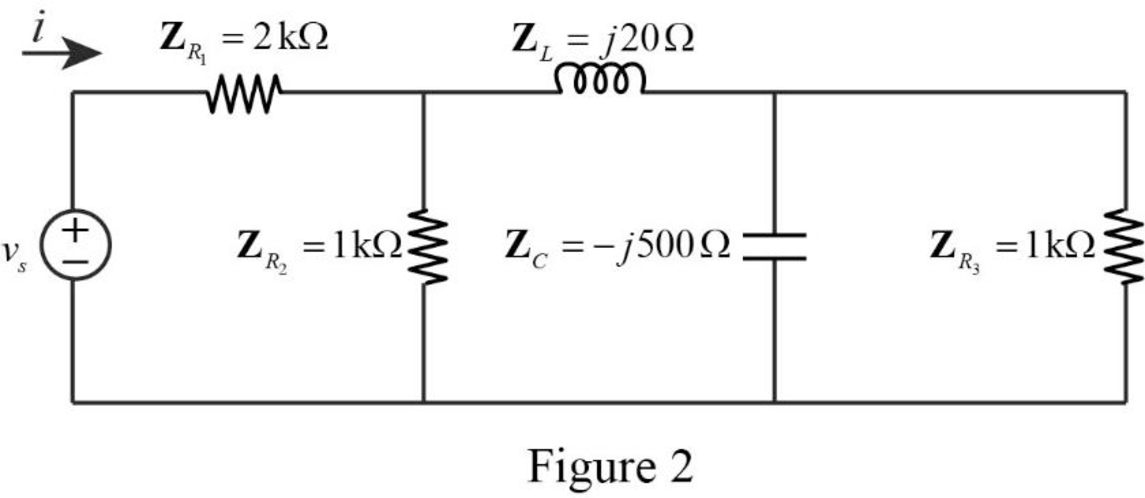
The reduced circuit of the Figure 2 is drawn as Figure 3.
Refer to Figure 3, the impedances
Write the expression to calculate the equivalent capacitance 2 for the series connected impedances
Here,
Substitute
The reduced circuit of the Figure 3 is drawn as Figure 4.
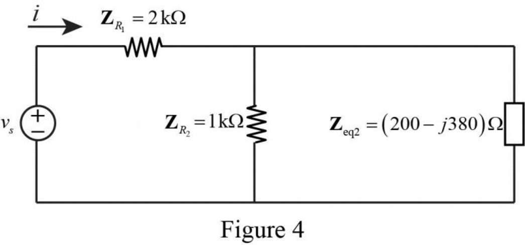
Refer to Figure 4, the impedances
Write the expression to calculate the equivalent capacitance 3 for the parallel connected impedances
Here,
Substitute
The reduced circuit of the Figure 4 is drawn as Figure 5.
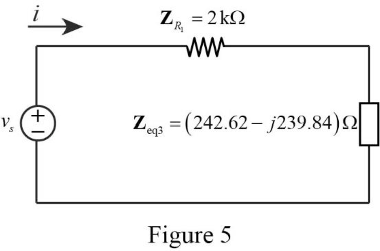
Refer to Figure 5, the impedances
Write the expression to calculate the equivalent capacitance 4 for the series connected impedances
Here,
Substitute
The reduced circuit of the Figure 5 is drawn as Figure 6.
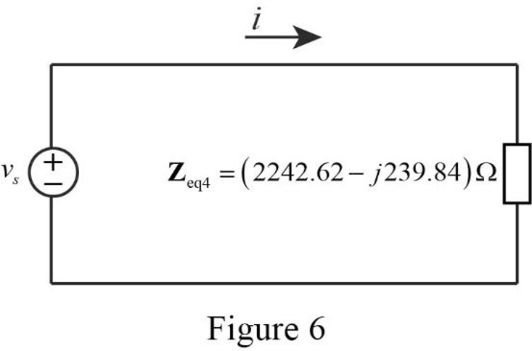
Therefore, the equivalent impedance of the circuit in Figure 1 is,
Substitute
Use the equation (1) to express the above equation in time domain form.
Substitute
Therefore, the value of current
Conclusion:
Thus, the problem to make better understand about the impedance using Figure 9.43 is designed.
Want to see more full solutions like this?
Chapter 9 Solutions
EBK FUNDAMENTALS OF ELECTRIC CIRCUITS
Additional Engineering Textbook Solutions
Basic Engineering Circuit Analysis
Principles and Applications of Electrical Engineering
ELECTRICITY FOR TRADES (LOOSELEAF)
Electric Motors and Control Systems
Engineering Electromagnetics
Introductory Circuit Analysis (13th Edition)


- Consider a sinusoidal emf source, v(t) = Vm sin (@t) results of current of i(t) = Im sin (@t+0) is applied to circuit of R, L & C in series. How to find the voltage across each one?.arrow_forward6. Find the characteristic impedance expression in terms of the inductance and capacitance parameters. a) Zo=√LC b) Zo=LC c) Zo=√L/C d) Zo=L/Carrow_forwardFind current i in the circuit of Fig. 9.42, when v, (t) = 50 cos200t V. 10 92 wwww 5 mF 20 mHarrow_forward
- 9.37 Determine the admittance Y for the circuit in Fig. 9.44. ... Y 2Ω j4 2 -j5 Q Figure 9.44 For Prob. 9.37. Answer in millisiemens. REAL IMAG (do not include "j" anymore) Y Blank 1 Blank 2 Blank 1 Add your answer Blank 2 Add your answer llarrow_forwardThe capacitive reactance is high when the capacitance and frequency of voltage source is high. Select one: True Falsearrow_forwardThe equivalent phasor domain representation of the equation of the current i = 60 Sin (100πt - 30°) mA isarrow_forward
- 9.65 Determine Z7 and I for the circuit in Fig. 9.72. 4Ω -j6 2 3Ω j4 Q 120/10° V ell ZT Figure 9.72arrow_forward70. Ideal inductors and capacitors are 90 degrees out of phase with each other. True False 71. Ideal inductors and resistors are 180 degrees out of phase with each other. True False 72. Impedance of a circuit can be represented or expressed in complex form. True Falsearrow_forwardA certain element has a phasor voltage of V = 200/30 V and current of I = 6Z120 A The angular frequency is 500 rad/s. Determine the nature of the element. The element is an inductance. • The element is a capacitance. The element is a resistance Previous Answers v Correctarrow_forward
- ELECTRICAL CIRCUIT: Solve the problem and show your complete solution. For the phasor diagram shown in the figure below, calculate the phase angle 0 between Is and Vs. |V,=9V VE2V Is V==7.5Varrow_forwardFind current in the circuit shown in Fig. 9.50.arrow_forwardAC circuits pQ Figure 9.30 For Practice Prob. 9.12. Find 1 in the circuit of Fig. 9.30. Answer: 9.546/33.8° A.arrow_forward
 Introductory Circuit Analysis (13th Edition)Electrical EngineeringISBN:9780133923605Author:Robert L. BoylestadPublisher:PEARSON
 Delmar's Standard Textbook Of ElectricityElectrical EngineeringISBN:9781337900348Author:Stephen L. HermanPublisher:Cengage Learning
 Programmable Logic ControllersElectrical EngineeringISBN:9780073373843Author:Frank D. PetruzellaPublisher:McGraw-Hill Education
 Fundamentals of Electric CircuitsElectrical EngineeringISBN:9780078028229Author:Charles K Alexander, Matthew SadikuPublisher:McGraw-Hill Education
 Electric Circuits. (11th Edition)Electrical EngineeringISBN:9780134746968Author:James W. Nilsson, Susan RiedelPublisher:PEARSON
 Engineering ElectromagneticsElectrical EngineeringISBN:9780078028151Author:Hayt, William H. (william Hart), Jr, BUCK, John A.Publisher:Mcgraw-hill Education,