
Videos
Prove that the magnitude M of the couple required to overcome the frictional resistance of a conical bearing as M=23μkPsinθR32−R31R22−R21.
Explanation of Solution
Write the equation of the magnitude of the couple as follows;
M=23μkPsinθR32−R31R22−R21
Here, the coefficient of kinetic friction is μk, the magnitude of the total axial force is P, the outer radii of the collar is R1, and the inner radii of the collar is R2.
Show the free-body diagram of the conical bearing as in Figure 1.
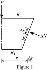
It has been assumed that the normal force per unit area is inversely proportional to r.
ΔA=rΔsΔϕ
Here, the distance between the point to the axis of the shaft is r, the change in distance is Δr, and the change in azimuthal angle is Δϕ.
Here, Δs=Δrsinθ
Find the normal force exerted ΔN due to the element of area ΔA using the relation;
ΔN=kΔA
Substitute rΔsΔϕ for ΔA.
ΔN=krΔsΔϕ
Substitute Δrsinθ for Δs.
ΔN=krΔrsinθΔϕ (1)
Find the change in friction force in y-axis;
ΔFy=ΔNsinθ
Substitute krΔrsinθΔϕ for ΔN.
ΔFy=krΔrsinθΔϕsinθ=krΔrΔϕ
Find the value of k using the relation.
P=∑ΔFy=∫2π0∫R2R1ΔFy
Substitute krΔrΔϕ for ΔFy.
P=∫2π0∫R2R1krΔrΔϕ=k[r22]R2R1[ϕ]2π0=k[R22−R212][2π]=πk(R22−R21)
k=Pπ(R22−R21)
Substitute Pπ(R22−R21) for k in Equation (1).
ΔN=Pπ(R22−R21)rΔrsinθΔϕ
Find the change in friction force ΔF using the relation.
ΔF=μkΔN
Substitute Pπ(R22−R21)rΔrsinθΔϕ for ΔN.
ΔF=μkPπ(R22−R21)rΔrsinθΔϕ
Find the change in moment ΔM using the relation.
ΔM=rΔF
Substitute μkPπ(R22−R21)rΔrsinθΔϕ for ΔF.
ΔM=rμkPπ(R22−R21)rΔrsinθΔϕ
Integrate the equation to find the couple M.
M=∫2π0∫R2R1ΔM
Substitute rμkPπ(R22−R21)rΔrsinθΔϕ for ΔM and integrate.
M=∫2π0∫R2R1rμkPπ(R22−R21)rΔrsinθΔϕ=μkPπsinθ(R22−R21)[r33]R2R1[ϕ]2π0=μkPπsinθ(R22−R21)[R32−R313][2π]=23μkPsinθ(R32−R31)(R22−R21)
Hence, it has been proved that the magnitude M of the couple required to overcome the frictional resistance of a conical bearing is M=23μkPsinθ(R32−R31)(R22−R21).
Want to see more full solutions like this?
Chapter 8 Solutions
Vector Mechanics for Engineers: Statics and Dynamics


- Consider a stainless steel spoon (k = 8.7 Btu/h·ft·°F) partially immersed in boiling water at 200°F in a kitchen at 75°F. The handle of the spoon has a cross section of 0.08 in × 0.5 in and extends 7 in in the air from the free surface of the water. The heat transfer coefficient at the exposed surfaces of the spoon handle is 3 Btu/h·ft2·°F. NOTE: This is a multi-part question. Once an answer is submitted, you will be unable to return to this part. A spoon is placed inside the container, such that the distance of the water level from the top end of the handle of the spoon is 7 meters. T sub air is indicated in the region outside the container. Identify the assumptions required to solve the problem. Check All That Apply One-dimensional heat transfer analysis is used to solve the problem. One-dimensional heat transfer analysis is used to solve the problem. Bi-dimensional heat transfer analysis is used to solve the problem. Bi-dimensional heat transfer analysis is…arrow_forwardA turbine blade made of a metal alloy (k=17 W/m-K) has a length of 5.3 cm, a perimeter of 11 cm, and a cross-sectional area of 5.13 cm². The turbine blade is exposed to hot gas from the combustion chamber at 1133°C with a convection heat transfer coefficient of 538 W/m²K. The base of the turbine blade maintains a constant temperature of 450°C and the tip is adiabatic. NOTE: This is a multi-part question. Once an answer is submitted, you will be unable to return to this part. Hot gas h=538 W/m²K -Turbine blade k = 17 W/m-K p=11 cm, L=5.3 cm A = 5.13 cm² -T=450°C Determine the heat transfer rate to the turbine blade. W. The heat transfer rate isarrow_forwardConsider a very long, slender rod. One end of the rod is attached to a base surface maintained at Tb, while the surface of the rod is exposed to an air temperature of 400°C. Thermocouples imbedded in the rod at locations 25 mm and 120 mm from the base surface register temperatures of 325°C and 375°C, respectively. NOTE: This is a multi-part question. Once an answer is submitted, you will be unable to return to this part. . x1 32 x Calculate the rod base temperature (°C). The rod base temperature is °C. Air T∞arrow_forward
- A rotating shaft of 20 mm diameter is simply supported. The shaft is loaded with a transverse load of 10 kN as shown in the figure. The shaft is made from AISI 1095 hot-rolled steel. The surface has been machined. The shaft operate at temperature T = 450 °C. Consider a reliability factor of 95%. Determine (a) Calculate the reaction forces R, and R₂ (2 points) (b) Draw the shear force and bending moment diagrams and determine the maximum bending moment and shear force. (6 points) 200 mm 20 mm 10,000 N -50 mm- A Not to scale. (c) Determine the critical location of the shaft and the maximum effective stresses. (3 points) (d) Calculate the safety factor against yielding. Does the shaft undergo local yielding? (2 points) (e) Determined the endurance limit, adjusted as necessary with Marin factors. (12 points) (f) Calculate the fatigue factor of safety based on achieving infinite life. (2 points) (g) If the fatigue factor of safety is less than 1 (hint: it should be for this problem), then…arrow_forward(read image)arrow_forward(read image)arrow_forward
- 6: Refer to the figure.Given: W1 = 200 kN/m; W2 = 300 kN/m; L1 = 2 m; L2 = 3 m; L3 = 2 m(a) Calculate the total length L so that the resulting upward pressureq is uniform. (b) draw the shear and moment diagram and determinethe maximum shear, maximum positive and negative bendingmoments.arrow_forwardA six cylinder, four-stroke diesel engine develops a power of 200 kW at 2000 rpm. The bsfc is 0.2 kW/kg h of fuel with 34.9° API. The fuel is injected at an average pressure of 350 bar and the pressure in the combustion chamber is 40 bar. Assuming Ca for injector 0.75 and the atmospheric pressure 1 bar. Determine the period of injection in seconds if the total orifice area required per injector is 0.4876 × 10⁻⁶ m².arrow_forwardTrieed a detailed drawing Win explanatio LL Antsmi 1981x pu + 96252 اه 6. The Pre-combustion chamber design engines employ nozzle type commonly referred to as a ....... a. inward-opening nozzle b. multiple-hole nozzle. c. pintle nozzle. d. none of these. 7. If the temperature of the spark plug tip is less than 350 °C, ......... a. the plug might not work. b. the carbon deposits would increase. 8. Port injection sprays fuel....... c. pre-ignition will occur. d. none of these. a. towards the intake valve. b. in the engine cylinder. c. in the throttle body assembly. d. none of these. 9. When the fuel-air mixture changed from best power to a richer ratio, the spark advance should be........ a. increased. b. decreased. c. left unchanged. d. none of these. d. none of these. 10. Spark plugs are classified as hot plugs and cold plugs depending upon ........ a. spark gap. b. the type of plug c. the operating temperature insulator. range of the electrode tip. ---20125 750 x2.01 SP 5.arrow_forward
 Elements Of ElectromagneticsMechanical EngineeringISBN:9780190698614Author:Sadiku, Matthew N. O.Publisher:Oxford University Press
 Mechanics of Materials (10th Edition)Mechanical EngineeringISBN:9780134319650Author:Russell C. HibbelerPublisher:PEARSON
 Thermodynamics: An Engineering ApproachMechanical EngineeringISBN:9781259822674Author:Yunus A. Cengel Dr., Michael A. BolesPublisher:McGraw-Hill Education
 Control Systems EngineeringMechanical EngineeringISBN:9781118170519Author:Norman S. NisePublisher:WILEY
 Mechanics of Materials (MindTap Course List)Mechanical EngineeringISBN:9781337093347Author:Barry J. Goodno, James M. GerePublisher:Cengage Learning
 Engineering Mechanics: StaticsMechanical EngineeringISBN:9781118807330Author:James L. Meriam, L. G. Kraige, J. N. BoltonPublisher:WILEY