Concept explainers
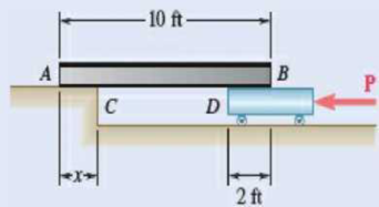
(a) Show that the beam of Prob. 8.41 cannot be moved if the top surface of the dolly is slightly lower than the platform. (b) Show that the beam can be moved if two 175-lb workers stand on the beam at B, and determine how far to the left the beam can be moved.
8.41 A 10-ft beam, weighing 1200 lb, is to be moved to the left onto the platform as shown. A horizontal force P is applied to the dolly, which is mounted on frictionless wheels. The coefficients of friction between all surfaces are μs = 0.30 and μs = 0.25, and initially, χ = 2 ft. Knowing that the top surface of the dolly is slightly higher than the platform, determine the force P required to start moving the beam. (Hint: The beam is supported at A and D.)

Fig. P8.41
(a)
Show that the beam cannot be moved if the top surface of the dolly is slightly lower than the platform.
Explanation of Solution
Given information:
The length of the beam is 10 ft.
The weight of the beam is
The coefficient of static friction between the surfaces is
The coefficient of kinetic friction between the surfaces is
Calculation:
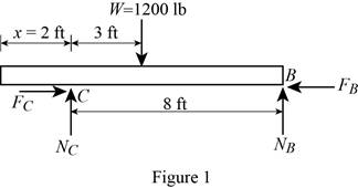
Show the free-body diagram of the beam AB as in Figure 1.

Find the normal force at point B by taking moment about end C.
Find the normal force at point C by resolving the vertical component of forces.
Find the maximum friction force at point C
Substitute 0.30 for
Find the maximum friction force at point B
Substitute 0.30 for
The maximum friction force at point B is less than the maximum friction force at point C.
The sliding is about to happen at point B.
Therefore, the beam
(b)
Show that the beam can be moved if two 175-lb workers stand on the beam at B.
Find the distance the beam moves to the left.
Answer to Problem 8.42P
The distance the beam moves to the left is
Explanation of Solution
Given information:
The length of the beam is 10 ft.
The weight of the beam is
The coefficient of static friction between the surfaces is
The coefficient of kinetic friction between the surfaces is
Calculation:
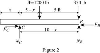
Show the free-body diagram of the beam AB as in Figure 2.

Find the normal force at point B by taking moment about end C.
Find the normal reaction at point C by taking moment about point B.
When two 175 lb workers stand on the end B:
Substitute 2 ft for x in Equation (1).
Substitute 2 ft for x in Equation (2).
Find the maximum friction force at point C
Substitute 0.30 for
Find the maximum friction force at point B
Substitute 0.30 for
The maximum friction force at point B is greater than the maximum friction force at point C.
The sliding is about to happen at point C.
Therefore, the beam
The beam will stop moving when the friction force at point C is equal to the maximum friction force at point B.
Find the friction force at point C
Substitute 0.25 for
Find the maximum friction force at point B
Substitute 0.30 for
Substitute
Therefore, the distance the beam moves to the left is
Want to see more full solutions like this?
Chapter 8 Solutions
Vector Mechanics for Engineers: Statics, 11th Edition
- Q.3) A luggage transport truck is used to raise and lower luggage from an aircraft. A piece of luggage weighing 450 lbs. is supported in the position shown with a center of gravity at point G. The raising and lowering mechanism are connected to the truck bed by a pin support at F and a roller support at H, and to the luggage platform by a pin support at C and a roller support at D. The hydraulic strut AB is pinned at either end and used to raise and lower the mechanism. Assume the weight of all members within the mechanism are negligible, that point C is vertically aligned with F, point D is vertically aligned with H, and that the strut AB is vertically 20maint oriented. (a) Determine the support reactions at F and H in the stationary position shown. (b) Determine the force in the hydraulic strut AB and state whether it is in tension or compression. 80000000 C 2.5 ft 0.5 ft 3 ft A B F G E H D 4 ft 4 ftarrow_forwardA 4 × 8-ft sheet of plywood weighing 34 lb has been temporarily placed among three pipe supports. The lower edge of the sheet rests on small collars at A and B and its upper edge leans against pipe C . Neglecting friction at all surfaces, determine the reactions at A, B and C.arrow_forward4.82 Determine the axle loads (normal forces at A, B, and C) for the ore hauler when it is parked on a horizontal roadway with its brakes off. The masses of the cab and the trailer are 4000 kg and 6000 kg, respectively, with centers of gravity at D and E. Assume that the connection at F is equivalent to a smooth pin. 2.4 m- -2m–|-1.5m-| 1m 0.6 m Fig. P4.82arrow_forward
- HELP ME!arrow_forwardLet us model the illustrated crusher as a planar mechanism that is subjected to the pushing force P on the lower "L-shaped" handle, i.e. link CDE. Note that link CDE is one solid piece, pinned at D and E. Knowing that the orange horizontal member AB has a square peg at A that slides vertically in the slot on the blue frame, that the can is centered under the pin at B and that P = 60 N, 0 = 15°, 6 = 10°, a = 60 mm, b = 230 mm, c = 60 mm, and d = 25 mm, determine the force magnitude F in N exerted on the can from the mechanism. F = d A Probably the l loger in th N arls rg a B E b P Carrow_forward9. A man is trying to pull the sled by applying a force of 500 N, as shown. The weight of the stone and the sled is 800 N while the sled is about to slide (i.e., it is still in equilibrium). Determine the magnitude of the reaction force R. a. b. W = 800 N 650 N 700 N 0 R P = 500 N 30⁰ Cc. d. 750 N 800 Narrow_forward
- Question 4: (a) (i) State the Principle of Moment (Varignon's Theorem). (ii) Prove that the moment of a couple is the same about any axis perpendicular to the plane of action of the couple. (b) A uniform rod Whose centre of gravity G divides it into the ratio AG : GB = a :b is in limiting equilibrium at an angle a with the horizontal with its upper end B resting against a smooth peg and its lower end A attached to a light cord, which is fastened to a point C on the same level as B. Prove that the angle B at which the cord is inclined to the horizontal is given by the equation a+b b tanß = tana cot a a a Question 5: (a) From Lesotho Bank tower an object was observed on the ground at a depression o below the horizon. A gun was fired at an elevation a, but the shot missing the object, stuck the ground at a point whose depression was y. Prove that the correct elevation 0 of the gun is given by sin(20 +0) + sin(o) sin(2a+0) + sin(o) sin y (1+ cos(20)) sin o (1+cos(2y))arrow_forwardA 10-ft boom is acted upon by the 840-lb force shown and is supported by a ball and socket at A. The tension in cable BE is: 6 ft 6 ft D. 7 ft A 6 ft 4 ft 840 lbarrow_forwardThe uniform 10 kg rod AB is supported by a ball and socket joint at A and by the cord CG that is attached to the midpoint G of the rod. Knowing that the rod leans against a frictionless vertical wall at B and that the tension in the cord CG, TCG=52.1 N, determine the following a.) Which of the following best shows the equivalent force-couple set at point A of the tension at cord CG, TCG? Choices: a F= -36.8 N i + 24.5 N j - 27.6 N k M = -7.36 Nm i - 11.03 Nm j b F= -36.8 N i + 24.5 N j - 27.6 N k M = -7.36 Nm i - 29.4 Nm k c F= 36.8 N i - 24.5 N j + 27.6 N k M = 7.36 Nm i + 11.03 Nm j d F= 36.8 N i - 24.5 N j + 27.6 N k M = 7.36 Nm i + 29.4 Nm k b.) Which of the following moments is equal to zero? Choices: The moment of the tension in cord CG, TCG about point OThe moment of the tension in cord CG, TCG about point AThe moment of the tension in cord CG, TCG about point BThe moment of the tension in cord CG, TCG about axis ABarrow_forward
- Frames and Machinesarrow_forwardA mechanic is reinstalling a newly-sharpened blade on a lawn mower. A wedged-in block of wood at C prevents the blade from rotating as the 29-lb force is applied to the wrench handle. The blade is bolted to a bracket attached to the motor shaft O, which protrudes through the bracket and blade. Determine the normal force at C. State any assumptions. Does it matter whether the bolt at B is installed? 6.5" 2.02.0" 5.9" 29 lb Answer: Nc = i Ibarrow_forwardA freight wagon is at rest on a track at an angle of 25o to the vertical. The gross weight of the wagon and its load is 36kN and acts at a point 750 mm from the track, in the middle between the two axles. The wagon is held by a cable 600 mm from the track. Determine the traction on the cable and the reaction on each pair of wheels.arrow_forward
 Elements Of ElectromagneticsMechanical EngineeringISBN:9780190698614Author:Sadiku, Matthew N. O.Publisher:Oxford University Press
 Mechanics of Materials (10th Edition)Mechanical EngineeringISBN:9780134319650Author:Russell C. HibbelerPublisher:PEARSON
 Thermodynamics: An Engineering ApproachMechanical EngineeringISBN:9781259822674Author:Yunus A. Cengel Dr., Michael A. BolesPublisher:McGraw-Hill Education
 Control Systems EngineeringMechanical EngineeringISBN:9781118170519Author:Norman S. NisePublisher:WILEY
 Mechanics of Materials (MindTap Course List)Mechanical EngineeringISBN:9781337093347Author:Barry J. Goodno, James M. GerePublisher:Cengage Learning
 Engineering Mechanics: StaticsMechanical EngineeringISBN:9781118807330Author:James L. Meriam, L. G. Kraige, J. N. BoltonPublisher:WILEY


