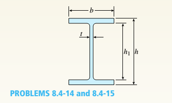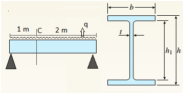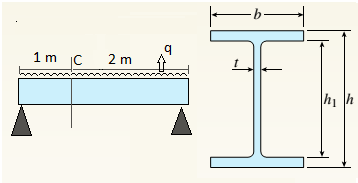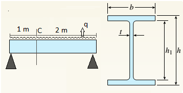
A beam with a wide-flange cross section (see figure) has the following dimensions: b = 5 in., t = 0.5 in,, ft = 12 in., and /?, = 10.5 in. The beam is simply supported with span length L = 10 ft and supports a uniform load q = 6 kips/fL
Calculate the principal stresses *rl and
[|] JA
3 ft from the left-hand support at each of the following locations: (a) the bottom of the beam, (b) the bottom of the web, and (c) the neutral axis
(a).
Find principal stresses and maximum shear stress at top of beam.
Answer to Problem 8.4.15P
Principal stresses
Maximum shear stress
Explanation of Solution
Given Information:
Beam length
Uniform load
Concept Used:
Bending stress
Shear stress
Principal normal stresses
Maximum shear stress

So bending moment at point
Shear force at point
Moment of inertia,
First moment of area at the top of beam shall be zero,
So bending stress at top,
And shear stress at that point,
For this situation no stress in
Principal normal stresses are given by following equation,
Maximum shear stress,
Conclusion:
Hence we get,
Principal stresses
Maximum shear stress
(b).
Find principal stresses and maximum shear stress at top of web.
Answer to Problem 8.4.15P
Principal stresses
Maximum shear stress
Explanation of Solution
Given Information:
Beam length
Uniform load
Concept Used:
Bending stress
Shear stress
Principal normal stresses
Maximum shear stress

So bending moment at point
Shear force at point
Moment of inertia,
First moment of area of flange,
So bending stress at top of web,
And shear stress at that point,
For this situation no stress in
Principal normal stresses are given by following equation,
Maximum shear stress,
Conclusion:
Hence we get,
Principal stresses
Maximum shear stress
(c).
Find principal stresses and maximum shear stress at neutral axis.
Answer to Problem 8.4.15P
Principal stresses
Maximum shear stress
Explanation of Solution
Given Information:
Beam length
Uniform load
Concept Used:
Bending stress
Shear stress
Principal normal stresses
Maximum shear stress

So bending moment at point
Shear force at point
Moment of inertia,
First moment of area for the section above the neutral axis,
So bending stress at neutral axis,
And shear stress at that point,
For this situation no stress in
Principal normal stresses are given by following equation,
Maximum shear stress,
Conclusion:
Hence we get,
Principal stresses
Maximum shear stress
Want to see more full solutions like this?
Chapter 8 Solutions
Mechanics of Materials (MindTap Course List)
- For the beam show below, draw A.F.D, S.F.D, B.M.D 6 kN/m 1 M B. 3 M Marrow_forward1. Two long rods of the same diameter-one made of brass (k=85w/m.k) and the other made of copper (k=375 w/m.k) have one of their ends inserted into a furnace (as shown in the following figure). Both rods are exposed to the same environment. At a distance of 105 mm from the furnace, the temperature of the brass rod is 120°C. At what distance from the furnace will the same temperature be reached in the copper rod? Furnace 105 mm T₁ Brass rod ⑪ h Too- x2- Ti Copper rodarrow_forward: +0 العنوان use only Two rods fins) having same dimensions, one made orass (k = 85 Wm K) and the mer of copper (k = 375 W/m K), having of their ends inserted into a furna. At a section 10.5 cm a way from furnace, the temperature of brass rod 120 Find the distance at which the ame temperature would be reached in the per rod ? both ends are ex osed to the same environment. ns 2.05 ۲/۱ ostrararrow_forward
- مشر on ۲/۱ Two rods (fins) having same dimensions, one made of brass(k=85 m K) and the other of copper (k = 375 W/m K), having one of their ends inserted into a furnace. At a section 10.5 cm a way from the furnace, the temperature brass rod 120°C. Find the distance at which the same temperature would be reached in the copper rod ? both ends are exposed to the same environment. 22.05 ofthearrow_forwardThe composite wall of oven with A= 1m² as in Fig.1 consists of three materials, two of with kA = 20 W/m K and kc = 50 W/m K with thickness, LA=0.3 m, L= 0.15 m and Lc 0.15 m. The inner surface temperature T1=900 K and the outer surface temperature T4 300 K, and an oven air temperature of To=1100 K, h=25 W/m². K. Determine kɛ and the temperatures T2 and T3 also draw the thermal resistance networkarrow_forwardTwo rods (fins) having same dimensions, one made of brass (k = 85 Wm K) and the other of copper (k = 375 W/m K), having one of their ends inserted into a furnace. At a section 10.5 cm a way from the furnace, the temperature of brass rod 120°C. Find the distance at which the same temperature would be reached in the copper rod ? both ends are exposed to the same environment. Ans 22.05arrow_forward
- A long wire (k-8 W/m °C.) with ro 5 mm and surface temperature Ts=180°C as shown in Fig.2. Heat is generated in the wire uniformly at a rate of 5 x10⁷ W/m³. If the energy equation is given by: d 11(77) + - =0 k r dr dr Derive an expression for T(r) and determine the temperature at the center of the wire and at r=2 mm. Air Th T KA LA T2 T3 T Fig.1 KB kc 180°C Го Fig.2arrow_forwardB: Find the numerical solution for the 2D equation below and calculate the temperature values for each grid point shown in Fig. 2 (show all steps). (Do only one trail using following initial values and show the final matrix) T₂ 0 T3 0 I need a real solution, not artificial intelligence locarrow_forwardCan I solve this problem by calculating the initial kinetic energy with respect to G instead of A.arrow_forward
- B: Find the numerical solution for the 2D equation below and calculate the temperature values for each grid point shown in Fig. 2 (show all steps). (Do only one trail using following initial values and show the final matrix) T₂ 0 T3 0 locarrow_forwardShow all work. Indicate the origin that is used for each plane. Identify the Miller indices for the following planes. N 23 1 A) X B) yarrow_forwardthe following table gives weight gain time data for the oxidation of some metal at an elevated temperature W(mg/cm2). Time (min) 4.66 20 11.7 50 41.1 175 a) determin whether the oxidation kinetics obey a linear, parabolic, or logarithmic rate expression. b) Now compute W after a time of 1000 minarrow_forward
 Mechanics of Materials (MindTap Course List)Mechanical EngineeringISBN:9781337093347Author:Barry J. Goodno, James M. GerePublisher:Cengage Learning
