Concept explainers
Videos
Programs DYNACAM and MATRIX may be used to solve these problems or to check your solution where appropriate.
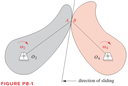
Figure P8-1 shows the cam and follower from Problem 6-65. Using graphical methods, find and sketch the equivalent fourbar linkage for this position of the cam and follower.
To sketch: The equivalent four bar linkage of thecam follower.
Explanation of Solution
Cams are rotated by cam pair at A and B. For an equivalent four bar linkage of cam and follower mechanism, the cam pair is converted into two turning pair by an imaginary link AB. Length of the link will be equal to the center of curvature distances between two cams. Also the two cam is replaced by a two links O2A and O2B. O2A is the distance between center of curvature of left cam at A and center of rotation of left cam at O2. Similarly O2B is distance between the center of curvature of right cam at B and center of rotation of right cam at O4.
Graphical method for four bar mechanism:-
- Take O2 and O4 as a fix link.
- Mark A and B as a center of curvature of the left and right cam respectively.
- Draw O2A and O2B and join A and B as AB.
Drawing the equivalent four bar linkage as shown below:
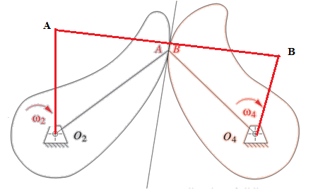
O2ABO4is the equivalent 4 bar linkage of two sliding cam mechanism. The angular velocity of left and right cam will be equal to the angular velocity of link O2A and O2B respectively.
Want to see more full solutions like this?
Chapter 8 Solutions
Design of Machinery


- Please don't provide handwritten solution.... Please I need to see the whole procedure. There are many similar problems but they calculate the velocity or acceleration, I need to calculate the positions, the time ratio and the stroke of link 6.arrow_forwardAll pertinent rigid dimensions are specified for the linkage shown. Note that the ground pivot for the input link is at the origin of the coordinate system. The input angle []in is currently 170° measured from the x axis as shown. The figure is not exactly to scale, but it is reasonably close for checking purposes. (a) Calculate the value of the angle []out as shown on the figure. Use the equations developed from the loop closure method. Note that you will need to incorporate a change of coordinate axes orientation to the axes defined for the loop closure equations. (b) Calculate the absolute location of point P with respect to the coordinate axes shown. 18 30° 9° 9 P 20 50° -170° Xarrow_forwardRe-work Problem 4 on Homework 2 using Lagrange's equations (see Figure 4 below). As indicated in the original problem statement, find the equations of motion and the constraint force (Hint: to find the constraint force, introduce an additional generalized coordinate and associated Lagrange multiplier).arrow_forward
- Evaluate the 3-DOF wrist as shown in Figure 2, use the conventional method to determine 1. Linear velocity and 2. Angular velocity NOTE: for JOINT 3 ( 03 ) only Connected to robot arm Pitch Roll Yaw Figure 2: Wrist assembly The known position and orientation of the end of the arm point is. C, C2 [-C,S2C3 + S¼S3 -S;S2C3 – C1S3 C2C3 C¡S2S3 + S1C3 S4S2S3 + C,C3 -C2S3 01 S,C2 S2 1 °T3=°T¡'T2²T3arrow_forward1. Find a combination of link lengths where motion of a point on output link is one quarter of a circle. 2. Find the value of all 0, 0, 0, and y in open and close configuration Read the value of link lengths and the input angle 8., then use the formulae given below to calculate the value of unknowns 03, 0, and y K₁ = = K₂= d K2 K3 = a²-b²+c²+d² 2ac A = cos 0₂ - K₁ - K₂ cos 0₂ + K3 B = -2 sin 0₂ C = K₁ (K₂ + 1) cos 02 + K3 -B± √B²-4AC 2A 0412 = 2tan-1 d K₁ = — K5 = c²d²a²-6² 2ab D = cos 0₂ - K₁ - K4 cos 0₂ + K5 E = -2 sin 0₂ FK₁+ (K₁ - 1) cos 02 +K5 0312 2 tan-1 (-E± -E± √E²4DF 2D Y = 04-03arrow_forwardThe link lengths, value of theta2, and offset for some fourbar slider-crank linkages are defined inTable P4-2. The linkage configuration and terminology are shown in Figure P4-2. For row a,draw the linkage to scale and graphically find all possible solutions (both open and crossed)for angles theta3 and slider position d.arrow_forward
- Consider the following 4 DOF manipulator. a) Assign the frames, and derive the link parameters in the DH table. b) Calculate the forward kinematics. c) Calculate the inverse kinematics of this robotic manipulator. ZU XH 4 YUarrow_forwardFigure out the 2D sketch of rocker using AutoCAD and mention all the dimensions. Colour the hatched lines which are inside the curve (red) 88 12R 2 holes 12 Dia 40 R 10RY 14R 80 100 34 R 89 120 15arrow_forwardA cam drive is used for mechanism that drives an automated assembly machine. The cam follower must rise outward 13 mm with constant velocity in 3 sec, dwell for 3 sec, fall 5 mm with constant acceleration in 2 sec, and then repeat the sequence. Determine the following for the given problems: 1. Calculate the time for a full cycle 2. Calculate the required rotational speed of the cam 3. Determine the cam rotation for each follower motion interval 4. Plot the displacement diagramarrow_forward
- Position Analysis of the crank-slider linkage. The link length and offset for a fourbar slider-crank linkage are: link 2= 3.5, link3= 10, offset=1. Find both open and crossed solutions for angle theta3 and slider position, d, as driver makes a complete revolution.construct graphs to describe how the slider and theta3 varies as theta2 makes the entire revolution.arrow_forwardThe general linkage configuration and terminology for an offset fourbar slider-crank linkage are shown in Figure below. The link lengths and the values of 02 and w2 are defined in. For the row(s) b and c, find the velocities of the pin joints A and B and the velocity of slip at the sliding joint using an analytical method. Draw the linkage to scale and label it before setting up the equations. y A 03 B Y 4 Link 3 A W2 Offset 02 04 = 90° Link 2 X 02 Slider position d TABLE P6-2 Data for Problems 6-6 to 6-7† Row Link 2 Link 3 Offset 02 02 a 1.4 4 1 45 10 2 -3 60 -12 3 8 2 -30 -15arrow_forwardThe link lengths and the value of 2 and offset for some fourbar crank-slide linkages are defined in Table 1. The linkage configuration and terminology are shown in Figure 1. For the rows assigned, find (a) all possible solutions for angle and slider position d by vector loop method. (b) the transmission angle corresponding to angle 83. (Hint: Treat the vector R4 as virtual rocker) Show your work in details: vector loop, vector equations, solution procedure. Table 1 Row a b с offset 02 Link 2 1.4 3 5 A R2 0₂ Link 3 4 8 20 slider axis. R3 Link 3 R₂ d R₁ Figure 1. 0₁ Offset 1 2 -5 С B R4 T 84 X Q2 45° -30° 225°arrow_forward
 Elements Of ElectromagneticsMechanical EngineeringISBN:9780190698614Author:Sadiku, Matthew N. O.Publisher:Oxford University Press
 Mechanics of Materials (10th Edition)Mechanical EngineeringISBN:9780134319650Author:Russell C. HibbelerPublisher:PEARSON
 Thermodynamics: An Engineering ApproachMechanical EngineeringISBN:9781259822674Author:Yunus A. Cengel Dr., Michael A. BolesPublisher:McGraw-Hill Education
 Control Systems EngineeringMechanical EngineeringISBN:9781118170519Author:Norman S. NisePublisher:WILEY
 Mechanics of Materials (MindTap Course List)Mechanical EngineeringISBN:9781337093347Author:Barry J. Goodno, James M. GerePublisher:Cengage Learning
 Engineering Mechanics: StaticsMechanical EngineeringISBN:9781118807330Author:James L. Meriam, L. G. Kraige, J. N. BoltonPublisher:WILEY