
Concept explainers
Videos
For the transistor configuration in Fig. 8.126:
a. Solve for the currents
b. Find the voltages
c. What is the ratio of output current
[Note: In transistor analysis, this ratio is referred to as the dc beta of the transistor (
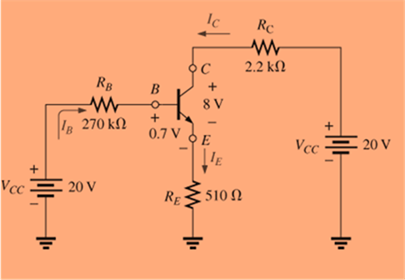
Fig. 8.126
Want to see the full answer?
Check out a sample textbook solution
Chapter 8 Solutions
Introductory Circuit Analysis (13th Edition)


- Subject : Power electronicsarrow_forward3. The network of Figure below is the basic biasing arrangement for the field-effect transistor (FET), a device of increasing importance in electronic design. (Biasing simply means the application of dc levels to establish a particular set of operating conditions.) Even though you may be unfamiliar with the FET, you can perform the following analysis using only the basic laws introduced in your lectures and the information provided on the diagram. a. Determine the voltages VG and Vs. b. Find the currents I1, I2, ID, and Is. c. Determine VDs. d. Calculate VDG- VDD = 16 V 오 |I1 ID R1 2 MN RD 2.5 kN 오D VGs = -1.75 V | I6 IG = 0 A = Is VGs -S |Is R2 270 kN %3D Rs 1.5 karrow_forward3. The network of Figure below is the basic biasing arrangement for the field-effect transistor (FET), a device of increasing importance in electronic design. (Biasing simply means the application of dc levels to establish a particular set of operating conditions.) Even though you may be unfamiliar with the FET, you can perform the following analysis using only the basic laws introduced in your lectures and the information provided on the diagram. a. Determine the voltages Vg and Vs. b. Find the currents I1, I2, ID, and Is. c. Determine VDS- d. Calculate VDG. VDD 오 16 V \ID R1 2 ΜΩ Rp 2.5 kN 오D VGO VGs = -1.75 V V GS S IG = 0 A o's Ip = Is R2 270 kN Is Rs 1.5 kNarrow_forward
- 3. The network of Figure below is the basic biasing arrangement for the field-effect transistor (FET), a device of increasing importance in electronic design. (Biasing simply means the application of dc levels to establish a particular set of operating conditions.) Even though you may be unfamiliar with the FET, you can perform the following analysis using only the basic laws introduced in your lectures and the information provided on the diagram. a. Determine the voltages VG and Vs. b. Find the currents I1, I2, Ip, and Is. c. Determine VDs. d. Calculate VDG. VDD = 16 V ID R132 MN R25 kN OD IG Vas = -1.75 V 4 Iç = 0A In = Is o's Is R2270 kN Rs1.5 kNarrow_forward3. The network of Figure below is the basic biasing arrangement for the field-effect transistor (FET), a device of increasing importance in electronic design. (Biasing simply means the application of dc levels to establish a particular set of operating conditions.) Even though you may be unfamiliar with the FET, you can perform the following analysis using only the basic laws introduced in your lectures and the information provided on the diagram. a. Determine the voltages VG and Vs. b. Find the currents I1, I2, Ip, and Is. c. Determine Vps. d. Calculate VDG- VDD 16 V ID 2 MN Rp32.5 kM R1 오D VGO G I IG VGs = -1.75 V IG = 0 A Ip = Is VGS oVs |Is R2 270 kN Rs 1.5 kNarrow_forwardHome Work & P1 For the following circuit, calculate the: a) Current in resistor R₁. through R8. b) Voltage between points X and as √xa. " a "b, Vab. ns: 39.375 V.-22.375 V X 90v R₂ R4 90k R3 Flok P2 For the following circuit, calculate : a) The supply voltage, ET. 120. [Ans: 201₂ 0.5A 1-52 +0 www d ET 2K www 523 12 R5 Sk R8 www 36.5kb 2012 ww tk -RET R₂ IKĮ -too MA loorarrow_forward
- Tutorial Problems As 1. For the circuit in Figure, find (a) 80a 200 100 fthe value of the supply voltage V (b) the value of currentarrow_forwardThe circuit below contains a nonlinear element N whose v-i relationship is given by the statement above the circuit in the image. With that in consideration, answer the following:1. Find the incremental change in iA (given by ia) for an incremental change in vI (given by vi). 2. Find the incremental change in iA for a 2% increase in the value of R. 3. Determine the incremental change in the voltage across the resistor R for an incremental change in the input vI (given by vi).arrow_forward8. b) Figure 8.b shows a f-v analogous electrical network of a mechanical system. Draw the corresponding mechanical system. M3 K2 K, M1 F =fm sincost D2 Figure 8.a L. R2 x(t) Figure 8.harrow_forward
- A power suppply having 220 V AC input and two fixed outputs as 10 V DC and 20 V DC is requested from you. For this purpose, a transformer with 220 V AC input / 15 V AC output, some capacitors, some silicon diodes, and zener diodes are presented. a) Design your power supply and point out DC voltage outputs b) Explain the operation of the network and all the components used in the design c) Calculate and plot input and output signals of the network Hint: For design, remember clipper, clamper, rectifier,voltage multiplier and zener circuitsarrow_forwardAn independent voltage source is characterized by a terminal voltage which Select one: a. is completely independent of the current through it. on b. is completely independent of the power dissipated by it. c. is completely dependent on the current through it. d. None of the abovearrow_forwardUse Multisim to implement CE setting up the rest point. Note: Use the value of the components that available in experiment's sheet.arrow_forward
 Delmar's Standard Textbook Of ElectricityElectrical EngineeringISBN:9781337900348Author:Stephen L. HermanPublisher:Cengage Learning