
Vector Mechanics for Engineers: Statics and Dynamics
12th Edition
ISBN: 9781259638091
Author: Ferdinand P. Beer, E. Russell Johnston Jr., David Mazurek, Phillip J. Cornwell, Brian Self
Publisher: McGraw-Hill Education
expand_more
expand_more
format_list_bulleted
Videos
Textbook Question
Chapter 7.1, Problem 7.5P
Determine the internal forces at point J when α = 90°.
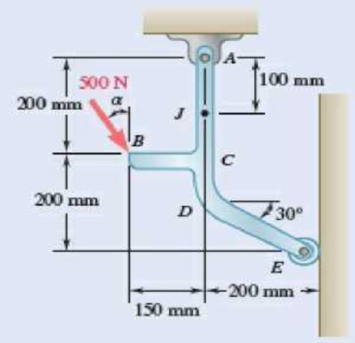
Fig. P7.5 and P7.6
Expert Solution & Answer
Want to see the full answer?
Check out a sample textbook solution
Students have asked these similar questions
Knowing that the radius of each pulley is 200 mm and neglecting friction. determine the internal forces at point K of the frame shown.Fig. P7.18
7.7 and 7.8 A half section of pipe rests on a horizontal surface as
shown. Knowing that the half section of the pipe has a mass of 9 kg and ne-
glecting friction between the pipe and the surface, determine the internal
forces at point J.
150 mm
Fig. P7.8
6.70 A uniform cable weighing 15 N/m is suspended from points A and B. The
force in the cable at B is known to be 500 N. Using the result of Prob. 6.69,
calculate (a) the force in the cable at A; and (b) the span L.
B
8 m
4 m
Fig. P6.70
Chapter 7 Solutions
Vector Mechanics for Engineers: Statics and Dynamics
Ch. 7.1 - 7.1 and 7.2 Determine the internal forces (axial...Ch. 7.1 - 7.1 and 7.2 Determine the internal forces (axial...Ch. 7.1 - Determine the internal forces at point J when =...Ch. 7.1 - Fig. P7.3 and P7.4 7.4 Determine the internal...Ch. 7.1 - Determine the internal forces at point J when =...Ch. 7.1 - Fig. P7.5 and P7.6 7.6 Determine the internal...Ch. 7.1 - An archer aiming at a target is pulling with a...Ch. 7.1 - For the bow of Prob. 7.7, determine the magnitude...Ch. 7.1 - A semicircular rod is loaded as shown. Determine...Ch. 7.1 - A semicircular rod is loaded as shown. Determine...
Ch. 7.1 - A semicircular rod is loaded as shown. Determine...Ch. 7.1 - Fig. P7.11 and P7.12 7.12 A semicircular rod is...Ch. 7.1 - The axis of the curved member AB is a parabola...Ch. 7.1 - Knowing that the axis of the curved member AB is a...Ch. 7.1 - Prob. 7.15PCh. 7.1 - Fig. P7.15 and P7.16 7.16 Knowing that the radius...Ch. 7.1 - Prob. 7.17PCh. 7.1 - For the frame of Prob. 7.17, determine the...Ch. 7.1 - Knowing that the radius of each pulley is 200 mm...Ch. 7.1 - Fig. P7.19 and P7.20 7.20 Knowing that the radius...Ch. 7.1 - and 7.22 A force P is applied to a bent rod that...Ch. 7.1 - and 7.22 A force P is applied to a bent rod that...Ch. 7.1 - Prob. 7.23PCh. 7.1 - For the rod of Prob. 7.23, determine the magnitude...Ch. 7.1 - A semicircular rod of weight W and uniform cross...Ch. 7.1 - Prob. 7.26PCh. 7.1 - Prob. 7.27PCh. 7.1 - 7.27 and 7.28 A half section of pipe rests on a...Ch. 7.2 - 7.29 through 7.32 For the beam and loading shown,...Ch. 7.2 - 7.29 through 7.32 For the beam and loading shown,...Ch. 7.2 - Prob. 7.31PCh. 7.2 - 7.29 through 7.32 For the beam and loading shown,...Ch. 7.2 - 7.33 and 7.34 For the beam and loading shown, (a)...Ch. 7.2 - 7.33 and 7.34 For the beam and loading shown, (a)...Ch. 7.2 - 7.35 and 7.36 For the beam and loading shown, (a)...Ch. 7.2 - Prob. 7.36PCh. 7.2 - 7.37 and 7.38 For the beam and loading shown, (a)...Ch. 7.2 - 7.37 and 7.38 For the beam and loading shown, (a)...Ch. 7.2 - For the beam and loading shown, (a) draw the shear...Ch. 7.2 - For the beam and loading shown, (a) draw the shear...Ch. 7.2 - Prob. 7.41PCh. 7.2 - For the beam and loading shown, (a) draw the shear...Ch. 7.2 - Assuming the upward reaction of the ground on beam...Ch. 7.2 - Solve Problem 7.43 knowing that P = 3wa. PROBLEM...Ch. 7.2 - Assuming the upward reaction of the ground on beam...Ch. 7.2 - Prob. 7.46PCh. 7.2 - Assuming the upward reaction of the ground on beam...Ch. 7.2 - Assuming the upward reaction of the ground on beam...Ch. 7.2 - Draw the shear and bending-moment diagrams for the...Ch. 7.2 - Draw the shear and bending-moment diagrams for the...Ch. 7.2 - Draw the shear and bending-moment diagrams for the...Ch. 7.2 - Draw the shear and bending-moment diagrams for the...Ch. 7.2 - Two small channel sections DF and EH have been...Ch. 7.2 - Solve Prob. 7.53 when = 60. PROBLEM 7.53 Two...Ch. 7.2 - For the structural member of Prob. 7.53, determine...Ch. 7.2 - For the beam of Prob. 7.43, determine (a) the...Ch. 7.2 - Determine (a) the distance a for which the maximum...Ch. 7.2 - For the beam and loading shown, determine (a) the...Ch. 7.2 - A uniform beam is to be picked up by crane cables...Ch. 7.2 - Knowing that P = Q = 150 lb, determine (a) the...Ch. 7.2 - Prob. 7.61PCh. 7.2 - Prob. 7.62PCh. 7.3 - Using the method of Sec. 7.3, solve Prob. 7.29....Ch. 7.3 - Prob. 7.64PCh. 7.3 - Prob. 7.65PCh. 7.3 - Using the method of Sec. 7.3, solve Prob. 7.32....Ch. 7.3 - Using the method of Sec. 7.3, solve Prob. 7.33....Ch. 7.3 - Using the method of Sec. 7.3, solve Prob. 7.34....Ch. 7.3 - 7.69 and 7.70 For the beam and loading shown, (a)...Ch. 7.3 - 7.69 and 7.70 For the beam and loading shown, (a)...Ch. 7.3 - Using the method of Sec. 7.3, solve Prob. 7.39....Ch. 7.3 - Using the method of Sec. 7.3, solve Prob. 7.40....Ch. 7.3 - Using the method of Sec. 7.3, solve Prob. 7.41....Ch. 7.3 - Using the method of Sec. 7.3, solve Prob. 7.42....Ch. 7.3 - 7.75 and 7.76 For the beam and loading shown, (a)...Ch. 7.3 - Prob. 7.76PCh. 7.3 - For the beam and loading shown, (a) draw the shear...Ch. 7.3 - For the beam and loading shown, (a) draw the shear...Ch. 7.3 - For the beam and loading shown, (a) draw the shear...Ch. 7.3 - For the beam and loading shown, (a) draw the shear...Ch. 7.3 - For the beam and loading shown, (a) draw the shear...Ch. 7.3 - For the beam and loading shown, (a) draw the shear...Ch. 7.3 - (a) Draw the shear and bending-moment diagrams for...Ch. 7.3 - Solve Prob. 7.83 assuming that the 300-lb force...Ch. 7.3 - For the beam and loading shown, (a) write the...Ch. 7.3 - For the beam and loading shown, (a) write the...Ch. 7.3 - For the beam and loading shown, (a) write the...Ch. 7.3 - Prob. 7.88PCh. 7.3 - The beam AB supports the uniformly distributed...Ch. 7.3 - Solve Prob. 7.89 assuming that the uniformly...Ch. 7.3 - The beam AB is subjected to the uniformly...Ch. 7.3 - Solve Prob. 7.91 assuming that the uniformly...Ch. 7.4 - Three loads are suspended as shown from the cable...Ch. 7.4 - Knowing that the maximum tension in cable ABCDE is...Ch. 7.4 - Prob. 7.95PCh. 7.4 - Fig. P7.95 and P7.96 7.96 If dA = dc = 6 ft,...Ch. 7.4 - Knowing that dc = 5 m, determine (a) the distances...Ch. 7.4 - Fig. P7.97 and P7.98 7.98 Determine (a) distance...Ch. 7.4 - Knowing that dc = 9 ft, determine (a) the...Ch. 7.4 - Fig. P7.99 and P7.100 7.100 Determine (a) the...Ch. 7.4 - Knowing that mB = 70 kg and mC = 25 kg, determine...Ch. 7.4 - Prob. 7.102PCh. 7.4 - Prob. 7.103PCh. 7.4 - Prob. 7.104PCh. 7.4 - Prob. 7.105PCh. 7.4 - If a = 4 m, determine the magnitudes of P and Q...Ch. 7.4 - An electric wire having a mass per unit length of...Ch. 7.4 - Prob. 7.108PCh. 7.4 - Prob. 7.109PCh. 7.4 - Prob. 7.110PCh. 7.4 - Prob. 7.111PCh. 7.4 - Two cables of the same gauge are attached to a...Ch. 7.4 - Prob. 7.113PCh. 7.4 - Prob. 7.114PCh. 7.4 - Prob. 7.115PCh. 7.4 - Prob. 7.116PCh. 7.4 - Prob. 7.117PCh. 7.4 - Prob. 7.118PCh. 7.4 - Prob. 7.119PCh. 7.4 - Prob. 7.120PCh. 7.4 - Prob. 7.121PCh. 7.4 - Prob. 7.122PCh. 7.4 - Prob. 7.123PCh. 7.4 - Prob. 7.124PCh. 7.4 - Prob. 7.125PCh. 7.4 - Prob. 7.126PCh. 7.5 - A 25-ft chain with a weight of 30 lb is suspended...Ch. 7.5 - A 500-ft-long aerial tramway cable having a weight...Ch. 7.5 - Prob. 7.129PCh. 7.5 - Prob. 7.130PCh. 7.5 - Prob. 7.131PCh. 7.5 - Prob. 7.132PCh. 7.5 - Prob. 7.133PCh. 7.5 - Prob. 7.134PCh. 7.5 - Prob. 7.135PCh. 7.5 - Prob. 7.136PCh. 7.5 - Prob. 7.137PCh. 7.5 - Prob. 7.138PCh. 7.5 - Prob. 7.139PCh. 7.5 - Prob. 7.140PCh. 7.5 - Prob. 7.141PCh. 7.5 - Prob. 7.142PCh. 7.5 - Prob. 7.143PCh. 7.5 - Prob. 7.144PCh. 7.5 - Prob. 7.145PCh. 7.5 - Prob. 7.146PCh. 7.5 - Prob. 7.147PCh. 7.5 - Prob. 7.148PCh. 7.5 - Prob. 7.149PCh. 7.5 - Prob. 7.150PCh. 7.5 - A cable has a mass per unit length of 3 kg/m and...Ch. 7.5 - Prob. 7.152PCh. 7.5 - Prob. 7.153PCh. 7 - Knowing that the turnbuckle has been tightened...Ch. 7 - Knowing that the turnbuckle has been tightened...Ch. 7 - Two members, each consisting of a straight and a...Ch. 7 - Knowing that the radius of each pulley is 150 mm,...Ch. 7 - Prob. 7.158RPCh. 7 - For the beam and loading shown, (a) draw the shear...Ch. 7 - For the beam and loading shown, (a) draw the shear...Ch. 7 - Prob. 7.161RPCh. 7 - Prob. 7.162RPCh. 7 - Prob. 7.163RPCh. 7 - Prob. 7.164RPCh. 7 - A 10-ft rope is attached to two supports A and B...
Knowledge Booster


Learn more about
Need a deep-dive on the concept behind this application? Look no further. Learn more about this topic, mechanical-engineering and related others by exploring similar questions and additional content below.Similar questions
- Problem 1.- A stake is being pulled out of the ground by means of two ropes as shown. Knowing that the tension in one rope is 120 N, determine by trigonometry the magnitude and direction of the force P so that the resultant is a vertical force of 160 N. Answer: P = 72.1 N and a = 44.7° %3D 120 N 25arrow_forward25 mm 60 mm 85 mm D 75 mm 6.136 The tongs shown are used to apply a total upward force of 45 ky on a pipe cap. Determine the forces exerted at D and F on tong ADF. E F 90 mm Fig. P6.136arrow_forwardKnowing that a worker applies forces of magnitude P = 135 N to the han- dles, determine the magnitude of the crimping forces that are exerted on the 140 The tool shown is used to crimp terminals onto electric wires. terminal. 30 +40- 200 B D F C E 15 Dimensions in mm -P Fig. P6.140arrow_forward
- 50 in. B 6.C1 For the loading shown, determine the force in each member of the truss as a function of the dimension a. Plot the force in each member for 40 In. as 240 in., with tensile forces plotted as positive and compressive forces as negative. 160 in. 25 kips Fig. P6.C1arrow_forwardSituation 10. A single force P acts at Cin a direction perpendicular to the handle BC of the crank shown. Knowing that M, +20 N – m, M, = -8.75 N – m and M, = -30 N – m, determine the magnitude of P and the values of o and 0 %3D 100 mm В 200 mm 150 mm xrarrow_forwardc. The maximum allowable tension in cable AC is 600 N and in cable BC is 750 N (fig. 1). Determine: The maximum force P that may be applied at C. The corresponding value of 6. i ii. 25arrow_forward
- If dC, = 15 ft. determine (a) : the distances dB and dD, (b) the inuximum tension in the cable.Fig. 7.99arrow_forwardPractice Problem 2.4.7: Knowing that the forces P and Q are equivalent to a single force R that passes through point A, Q = 30 lb 8.5 in. determine P. P 8 in. H 5 in. 35°arrow_forwardPROBLEM. The given frame is subjected to the applied loads of P and Q. Given: P=146.3 kN Q = 120.9 KN 0 = 41.82° 1. Draw the FBDs of all members. 2. Determine the force in each link- AF, BG, DG, and EH. Note: Neglect the weight of the members.arrow_forward
- 4.2 in. 8.4 in. 4.2 in 8.4 in. K J. D 5 in. 120 lb 2.7 in. - 12.6 in. 16.2 in. Fig. P7.11 and P7.12 7.12 Two members each consisting of straight and 8.4-in.-radius quarter-circle portions are connected as shown and support a 120-lb load at D. Determine the internal forces at point Karrow_forwardc. The maximum allowable tension in cable AC is 600 N and in cable BC is 750 N (fig. 1). Determine: i The maximum force P that may be applied at C. The corresponding value of 0. ii. B. 250arrow_forward6.139 A hand-operated hydraulic cylinder has been designed for uhe where space is severely limited. Determine the magnitude of the force ca erted on the piston at D when two 90-lb forces are applied as shown. 90 lb -4 in.- - 9.2 in.- |c A 0.9 in.f 2.4 in. 0.9 in.1 2.4 in. В E 2 in. 90 lb Fig. P6.139arrow_forward
arrow_back_ios
SEE MORE QUESTIONS
arrow_forward_ios
Recommended textbooks for you
 Elements Of ElectromagneticsMechanical EngineeringISBN:9780190698614Author:Sadiku, Matthew N. O.Publisher:Oxford University Press
 Mechanics of Materials (10th Edition)Mechanical EngineeringISBN:9780134319650Author:Russell C. HibbelerPublisher:PEARSON
 Thermodynamics: An Engineering ApproachMechanical EngineeringISBN:9781259822674Author:Yunus A. Cengel Dr., Michael A. BolesPublisher:McGraw-Hill Education
 Control Systems EngineeringMechanical EngineeringISBN:9781118170519Author:Norman S. NisePublisher:WILEY
 Mechanics of Materials (MindTap Course List)Mechanical EngineeringISBN:9781337093347Author:Barry J. Goodno, James M. GerePublisher:Cengage Learning
 Engineering Mechanics: StaticsMechanical EngineeringISBN:9781118807330Author:James L. Meriam, L. G. Kraige, J. N. BoltonPublisher:WILEY
Elements Of Electromagnetics
Mechanical Engineering
ISBN:9780190698614
Author:Sadiku, Matthew N. O.
Publisher:Oxford University Press
Mechanics of Materials (10th Edition)
Mechanical Engineering
ISBN:9780134319650
Author:Russell C. Hibbeler
Publisher:PEARSON
Thermodynamics: An Engineering Approach
Mechanical Engineering
ISBN:9781259822674
Author:Yunus A. Cengel Dr., Michael A. Boles
Publisher:McGraw-Hill Education
Control Systems Engineering
Mechanical Engineering
ISBN:9781118170519
Author:Norman S. Nise
Publisher:WILEY
Mechanics of Materials (MindTap Course List)
Mechanical Engineering
ISBN:9781337093347
Author:Barry J. Goodno, James M. Gere
Publisher:Cengage Learning
Engineering Mechanics: Statics
Mechanical Engineering
ISBN:9781118807330
Author:James L. Meriam, L. G. Kraige, J. N. Bolton
Publisher:WILEY
How to balance a see saw using moments example problem; Author: Engineer4Free;https://www.youtube.com/watch?v=d7tX37j-iHU;License: Standard Youtube License