(a)
The internal forces exerted at the point
(a)
Answer to Problem 7.15P
The internal forces of shearing force is
Explanation of Solution
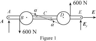
Sketch the free body diagram for the internal forces acting on the frame and pulley system as shown in the Figure 1.

Write the equation of the axial force exerted at the axial point
Here, the force exerted on the frame at the point
Write the equation of the moment of couple formed in the bending moment of the frame and pulley system supported at the point
Here, the axial force exerted on the pulley at point
Write the equation of the axial force exerted at the axial point of the frame from y direction (Refer fig 1).
Here, the axial force exerted on the pulley at point
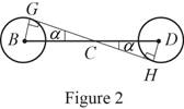
Sketch the free body diagram for the cable as shown in the Figure 2.

The slope of the cable (Refer fig 2):
The angle formed in the slope of the cable:
Rewrite the above relation to find the angle.
Write the equation of the axial force exerted at the axial point
Here, the angle between the pulley
Sketch the free body diagram for the cable for the point

Write the equation of the axial force exerted at the point
Here, shearing force acting on the semicircular rod is
At the pulley
Write the equation of the moment of couple formed in the bending moment supported at the point
Here, the moment of couple exerted at the point
Conclusion:
Substitute
Solve the above equation for
Substitute
Substitute
Substitute
Substitute
The above equation can be written as,
Therefore, the internal forces of shearing force is
(b)
The internal forces exerted at the point
(b)
Answer to Problem 7.15P
The internal forces of shearing force is
Explanation of Solution
Sketch the free body diagram for the cable for the point

Write the equation of the axial force exerted at the axial point
Here, the force exerted on the frame at the point
Write the equation of the axial force exerted at the axial point of the frame from y direction (Refer fig 4).
Here, the axial force exerted on the pulley at point
Write the equation of the moment of couple formed in the bending moment supported at the point
Here, the moment of couple exerted at the point
Conclusion:
Substitute
Substitute
Substitute
The above equation can be written as,
Therefore, the internal forces of shearing force is
Want to see more full solutions like this?
Chapter 7 Solutions
VECTOR MECH...,STAT.+DYN.(LL)-W/ACCESS
- Mp Fig. P8.126 8.127 Solve Prob. 8.126 assuming that u = 75°. B 8.128 The 10-lb bar AE is suspended by a cable that passes over a 5-in.- radius drum. Vertical motion of end E of the bar is prevented by the two stops shown. Knowing that m, = 0.30 between the cable and the drum, determine (a) the largest counterclockwise couple M, that can be applied to the drum if slipping is not to occur, (b) the corresponding force exerted on end E of the bar. A E 10 lb 5 in. 5 in. 3 in. Fig. P8.128arrow_forward6 .129arrow_forwardKnowing that the radius of each pulley is 150 mm, that a = 20°, and neglecting friction, determine the internal forces at (a) point J, (b) point K.arrow_forward
- 6.142 A locking C-clamp is used to clamp two pieces of -in. steel plate. Determine the magnitude of the gripping forces produced when two 30-lb forces are applied as shown. -2.6 in.- -1.9 in. -1.3 in.- |30 lb A Bo + 0.85 in. 0.3 in. -2.6 in.- 30 lb 0.8 in. Fig. P6.142arrow_forwardKnowing that a worker applies forces of magnitude P = 135 N to the han- dles, determine the magnitude of the crimping forces that are exerted on the 140 The tool shown is used to crimp terminals onto electric wires. terminal. 30 +40- 200 B D F C E 15 Dimensions in mm -P Fig. P6.140arrow_forwardDetermine the range of the force Of for which the system will be at rest.arrow_forward
- The cylinder shown is of weight W and radius r . Express in terms XV and r the magnitude of the largest couple M that can be applied to the cylinder if it is not to rotate, assuming the coefficient of static friction to be (a) zero at A and 0.30 at B, (b) 0.25 at A and 0.30 at B.Fig. P8.18arrow_forward8.59 A 6° steel wedge is driven into the end of an ax handle to lock the handle to the ax head. The coefficient of static friction between the wedge and the handle is 0.35. Knowing that a force P of magnitude 60 lb was re- quired to insert the wedge to the equilibrium position shown, determine the magnitude of the forces exerted on the handle by the wedge after force P is removed. Fig. P8.59arrow_forwardProblem 8.37 from Ferdinand Beerarrow_forward
- 25 mm 60 mm 85 mm D 75 mm 6.136 The tongs shown are used to apply a total upward force of 45 ky on a pipe cap. Determine the forces exerted at D and F on tong ADF. E F 90 mm Fig. P6.136arrow_forwardThe telescoping arm ABC of Prob. 6.93 can be lowered until end C is close to the ground, so that workers can easily board the platform.For the position when θ = -220°, determine (a) the force exerted at B by the single hydraulic cylinder BD, (b) the force exerted on the supporting carriage at A.arrow_forward1arrow_forward
 Elements Of ElectromagneticsMechanical EngineeringISBN:9780190698614Author:Sadiku, Matthew N. O.Publisher:Oxford University Press
 Mechanics of Materials (10th Edition)Mechanical EngineeringISBN:9780134319650Author:Russell C. HibbelerPublisher:PEARSON
 Thermodynamics: An Engineering ApproachMechanical EngineeringISBN:9781259822674Author:Yunus A. Cengel Dr., Michael A. BolesPublisher:McGraw-Hill Education
 Control Systems EngineeringMechanical EngineeringISBN:9781118170519Author:Norman S. NisePublisher:WILEY
 Mechanics of Materials (MindTap Course List)Mechanical EngineeringISBN:9781337093347Author:Barry J. Goodno, James M. GerePublisher:Cengage Learning
 Engineering Mechanics: StaticsMechanical EngineeringISBN:9781118807330Author:James L. Meriam, L. G. Kraige, J. N. BoltonPublisher:WILEY


