
Concept explainers
Videos
7.13 through 7.16 For the given state of stress, determine the normal and shearing stresses after the element shown has been rotated through (a) 25° clockwise, (b) 10° counterclockwise.
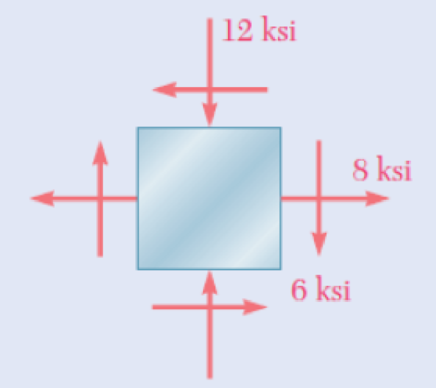
Fig. P7.15
(a)
The normal and shearing stresses after the element has been rotated through
Answer to Problem 15P
The normal stresses are
The shear stress is
Explanation of Solution
Given information:
The stress component along x direction as
The stress component along y direction as
The shear stress component as
The orientation of the principal plane as
Calculation:
Calculate the normal stress along x direction
Substitute
Hence, the normal stress as
Calculate the normal stress along y direction
Substitute
Hence, the normal stress as
Calculate the shear stress
Substitute
Therefore, the shear stress as
(b)
The normal and shearing stresses after the element has been rotated through
Answer to Problem 15P
The normal stresses are
The shear stress is
Explanation of Solution
Given information:
The stress component along x direction as
The stress component along y direction as
The shear stress component as
The orientation of the principal plane as
Calculation:
Calculate the normal stress along x direction
Substitute
Hence, the normal stress as
Calculate the normal stress along y direction
Substitute
Hence, the normal stress as
Calculate the shear stress
Substitute
Therefore, the shear stress as
Want to see more full solutions like this?
Chapter 7 Solutions
Mechanics of Materials, 7th Edition


- In many situations it is known that the normal stress in a given direc-tion is zero. For example, σz= 0 in the case of the thin plate shown. For this case, which is known as plane stress, show that if the strains εx and εy have been determined experimentally, we can express σx, σyand εz as follows:arrow_forwardStraight rods of 0.30-in. diameter and 200-ft length are sometimes used to clear underground conduits of obstructions or to thread wires through a new conduit. The rods are made of high-strength steel and, for storage and transportation, are wrapped on spools of 5-ft diameter. Assuming that the yield strength is not exceeded, determine (a) the maximum stress in a rod, when the rod, which was initially straight, is wrapped on the spool, (b) the corresponding bending moment in the rod. Use E= 29 * 106 psi.arrow_forwardThe storage tank shown contains liquefied propane under a pressure of 1.4 MPa at a temperature of 38 °C . Knowing that the tank has a diameter of 315 mm and a wall thickness of 2.8 mm determinethe maximum normal stress and the maximum shearing stress in the tank.arrow_forward
- A fabric used in air-inflated structures is subjected to a biaxial loading that results in normal stresses ox = 18 ksi and oz = 24 ksi.Knowing that the properties of the fabric can be approximated as E = 12.6 x 10 psi and v = 0.34, determine the change in length of (a) side AB, (b) side BC, (c) diagonal AC.arrow_forwardA steel pipe of 400-mm outer diameter is fabricated from 10-mm-thick plate by welding along a helix that forms an angle of 20°with a plane perpendicular to the axis of the pipe. Knowing that the maximum allowable normal and shearing stresses in the directions respectively normal and tangential to the weld are σ = 60 MPa and τ = 36 MPa, determine the magnitude P of the largest axial force that can be applied to the pipe.arrow_forward6. A strain gage located at C on the surface of bone AB indicates that the average normal stress in the bone is 3.80 MPa when the bone is subjected to two 1200-N forces as shown. Assuming the cross section of the bone at C to be annular and knowing that its outer diameter is 25 mm, determine the inner diameter of the bone’s cross section at C.arrow_forward
- A torque of magnitude T=12 kN·m is applied to the end of a tank containing compressed air under a pressure of 8 MPa. Knowing that the tank has a 180-mm inner diameter and a 12-mm wall thickness, determine the maximum normal stress and the maximum in-plane shearing stress in the tank.arrow_forwardEach of the four vertical Ilinks has an 8 x 36-mm uniform rectangular cross section and each of the four pins has a 16-mm diameter. Take P= 19 kN. 0.4 m C 0.25 m 0.2 m B. P Determine the average bearing stress at Bin member ABC, knowing that this member has a 10 x 50-mm uniform rectangular cross section. MPa. The average bearing stress at Bin member ABC is.arrow_forwardShow that the angle between the plane of the major principal stress and the plane of the maximum shear stress is 45° for any state of stress.arrow_forward
- For the truss and loading shown, determine the magnitude of the normal stress(in psi) in member CE, knowing that the cross-sectional area of that member is 3.67 in2 if P = 30505 lb, Q = 34758 lb, and y = 7.35 ft. Round off the final answer to two decimal places.arrow_forwardA timber beam AB of length L and rectangular cross section carries a single concentrated load P at its midpoint C. (a) Show that the ratio Tm/ m of the maximum values of the shearing and normal stresses in the beam is equal to h/2L, where h and L are, respectively, the depth and the length of the beam. (b) Determine the depth h and the width b of the beam, knowing that L = 2 m, P = 40 kN, 7m = 960 kPa, and om = 12 MPa.arrow_forwardAt a temperature of 28.75 °C a 0.4-mm gap exists between the ends of the rods shown. At a later time when the temperature has reached 123.11°C, determine the magnitude of the normal stress (in MPa) in the steel rod if L = 306.57 mm and M = 203 mm. Round off the final answer to four decimal places.arrow_forward
 Elements Of ElectromagneticsMechanical EngineeringISBN:9780190698614Author:Sadiku, Matthew N. O.Publisher:Oxford University Press
 Mechanics of Materials (10th Edition)Mechanical EngineeringISBN:9780134319650Author:Russell C. HibbelerPublisher:PEARSON
 Thermodynamics: An Engineering ApproachMechanical EngineeringISBN:9781259822674Author:Yunus A. Cengel Dr., Michael A. BolesPublisher:McGraw-Hill Education
 Control Systems EngineeringMechanical EngineeringISBN:9781118170519Author:Norman S. NisePublisher:WILEY
 Mechanics of Materials (MindTap Course List)Mechanical EngineeringISBN:9781337093347Author:Barry J. Goodno, James M. GerePublisher:Cengage Learning
 Engineering Mechanics: StaticsMechanical EngineeringISBN:9781118807330Author:James L. Meriam, L. G. Kraige, J. N. BoltonPublisher:WILEY