
Concept explainers
Videos
Equipment ratings for the five-bus power system shown in Figure 7.15 are as follows:
Generator G1:    50 MVA, 12kV,Â
Generator G2: 100Â MVA, 15 kV,
Transformer T1: 50 MVA, 10 kV
Transformer T2: 100 MVA, 15 kV
Each 138-kV line:
A three-phase short circuit occurs at bus 5, where the prefault voltage is 15 kV. Prefault load current is neglected. (a) Draw the positive-sequence reactance diagram in unit on a 100-MVA, 15-kV base in the zone of generator G2. Determine (b) the ThĂ©venin equivalent at the fault, (c) the subtransient fault current in per unit and in kA rms, and (d) contributions to the fault from generator G2 and from transformer T2. 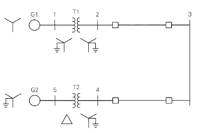

Trending nowThis is a popular solution!

Chapter 7 Solutions
Power System Analysis and Design (MindTap Course List)


- The per-unit equivalent circuit of two transformers Ta and Tb connected in parallel, with the same nominal voltage ratio and the same reactan of 0.1 per unit on the same base, is shown in Figure 3.43. Transformer Tb has a voltage-magnitude step-up toward the load of 1.05 times that of Ta (that is, the tap on the secondary winding of Tb is set to 1.05). The load is represented by 0.8+j0.6 per unit at a voltage V2=1.0/0 per unit. Determine the complex power in per unit transmitted to the load through each transformer, comment on how the transformers share the real and reactive powers.arrow_forwardEquipment ratings for the four-bus power system shown in Figure 7.14 are as follows: Generator G1: 500 MVA, 13.8 kV, X=0.20 per unit Generator G2: 750 MVA, 18 kV, X=0.18 per unit Generator G3: 1000 MVA, 20 kV, X=0.17 per unit Transformer T1: 500 MVA, 13.8/500YkV,X=0.12 per unit Transformer T2: 750 MVA, 18/500YkV,X=0.10 per unit Transformer T3: 1000 MVA, 20/500YkV,X=0.10 per unit A three-phase short circuit occurs at bus 1, where the prefault voltage is 525 kV. Prefault load current is neglected. Draw the positive-sequence reactance diagram in per unit on a 1000-MVA, 20-kV base in the zone of generator G3. Determine (a) the Thévenin reactance in per unit at the fault, (b) the subtransient fault current in per unit and in kA rms, and (c) contributions to the fault current from generator G1 and from line 1-2.arrow_forwardConsider the oneline diagram shown in Figure 3.40. The three-phase transformer bank is made up of three identical single-phase transformers, each specified by X1=0.24 (on the low-voltage side), negligible resistance and magnetizing current, and turns ratio =N2/N1=10. The transformer bank is delivering 100 MW at 0.8 p.f. lagging to a substation bus whose voltage is 230 kV. (a) Determine the primary current magnitude, primary voltage (line-to-line) magnitude, and the three-phase complex power supplied by the generator. Choose the line-to-neutral voltage at the bus, Va as the reference Account for the phase shift, and assume positive-sequence operation. (b) Find the phase shift between the primary and secondary voltages.arrow_forward
- In developing per-unit circuits of systems such as the one shown in Figure 3.10. when moving across a transformer, the voltage base is changed in proportion to the transformer voltage ratings. (a) True (b) Falsearrow_forwardThree single-phase two-winding transformers, each rated 25MVA,54.2/5.42kV, are connected to form a three-phase Y- bank with a balanced Y-connected resistive load of 0.6 per phase on the low-voltage side. By choosing a base of 75 MVA (three phase) and 94 kV (line-to-line) for the high-voltage side of the transformer bank, specify the base quantities for the low-voltage side. Determine the per-unit resistance of the load on the base for the low-voltage side. Then determine the load resistance RL in ohms referred to the high-voltage side and the per-unit value of this load resistance on the chosen base.arrow_forwardFigure 3.39 shows a oneline diagram of a system in which the three-phase generator is rated 300 MVA, 20 kV with a subtransient reactance of 0.2 per unit and with its neutral grounded through a 0.4- reactor. The transmission line is 64km long with a cries reactance of 0.5-/km. The three-phase transformer T1 is rated 350MVA.230/20kV with a leakage reactance of 0.1 per unit. Transformer T2 is composed of three single-phase transformers, each rated 100 MVA, 127/13.2kV with a leakage reactance of 0.1 per unit. Two 13.2kV motors M1 and M2 with a subtransient reactance of 0.2 per unit for each motor represent the load. M1 has a rated input of 200 MVA with its neutral grounded through a 0.4- current-limiting reactor, M2 has a rated input of 100 MVA with its neutral not connected to ground. Neglect phase shifts associated with the transformers. Choose the generator rating as base in the generator circuit and draw the positive-sequence reactance diagram showing all reactances in per unit.arrow_forward
- b) A fault occurs at bus 3 of the network shown in Figure Q4. Pre-fault nodal voltages throughout the network are of 1 p.u. and the impedance of the electric arc is neglected. Sequence impedance parameters of the generator, transmission lines, transformer and load are given in Figure Q4. V₁ = 120° p.u. V₂ = 120° p.u. V₂ = 1/0° p.u. V₂= 120° p.u. jXj0.1 p.u. JX2) 0.1 p.u. jX0j0.15 p.u. jXn-j0.2 p.u. 1 JX(2)-j0.2 p.u. 2 jX)=j0.25 p.u. JX20-10.15 p.u. jXa(z)-j0.2 p.u. 4 jX2(0)=j0.2 p.u. jXT(1) j0.1 p.u. jXT(2)=j0.15 p.u. jXT(0)=j0.1 p.u. Figure Q4. Circuit for problem 4b). = jXj0.1 p.u. j0.1 p.u. - JX(2) JXL(0) 10.1 p.u. = (i) Assuming a balanced excitation, draw the positive, negative and zero sequence Thévenin equivalent circuits as seen from bus 3. (ii) Determine the positive sequence fault current for the case when a three- phase-to-ground fault occurs at bus 3 of the network. (iii) Determine the short-circuit fault current for the case when a one-phase- to-ground fault occurs at bus…arrow_forwardThree zones of a single-phase circuit are identified in Figure. The zones are connected bytransformers T1 and T2, whose ratings are also shown.Using base values of 30 kVA and 240 volts in zone 1:a. draw the per-unit circuit and determine the per-unit impedances and the per-unitsource voltage.b. calculate the load current both in per-unit and in amperes. Transformer windingresistances and shunt admittance branches are neglected.arrow_forwardFIGURE Q2 shows a four bus three phase power system. The generators, transformers and transmission line per unit reactance are given as follows: Generator G1, G2: XG= 0.05 pu Transformers T1, T2: XT= 0.13 pu Transmission Line 2 – 3: XL = 0.50 pu Bus 1 Bus 2 Bus 3 Bus 4 Line GI T1 G2 FAULT FIGURE Q2 Evaluate the per unit fault current, fault MVA and voltage at all buses if a three phase bolted fault occurs at Bus 2.arrow_forward
- b) A fault occurs at bus 2 of the network shown in Figure Q3. Pre-fault nodal voltages throughout the network are of 1 p.u. and the impedance of the electric arc is neglected. Sequence impedance parameters of the generator, transmission lines, and transformer are given in Figure Q3, where X and Y are the last two digits of your student number. JX20 /0.1X p.u. jXa2) 0.1X p.u. JX20 j0.2Y p.u. V,= 120° p.u. V, 120° p.u. V, 120° p.u. jX4-70.2X p.u. jX2 j0.2X p.u. jX o 0.2Y p.u. jXncay J0.25 p.u. jXna J0.25 p.u. 3 jXno0.3 p.u. jXTu) /0.2Y p.u. jXra j0.2Y p.u. - j0.2Y p.u. Xp-10.1X p.u. jXa j0.1X p.u. jXp0)- j0.05 p.u. 0 Figure Q3. Circuit for problem 3b). For example, if your student number is c1700123, then: jXac1) = j0.22 p.u., jXac2) = j0.22 p.u., and jXaco) = j0.23 p. u. X-2 Y=8 (iv) Determine the short-circuit fault current for the case when a phase-to- phase fault occurs at bus 2.arrow_forwardQ2) In the network in the figure below Y-Y connected transformers, each with grounded neutrals, are at the ends of each transmission line that is not terminating at bus 3. The transformers connecting the lines to bus 3 are Y-A, with the neutral of the Y solidly grounded and the A sides connected to bus 3. All the line reactances shown in the figure between busses include the reactances of the transformers. Zero sequence values for these lines including transformers are 2.0 times those shown in the figure. Both generators are Y-Connected. Zero-sequence reactances of the generators connected to bus 1 and bus 3 are 0.04 and 0.08 per unit, respectively. The neutral of the generator at bus 1 is connected to ground through a reactor of 0.02 per unit; the generator at bus 3 has a solidly ground neutral. Find the bus impedance matrices (¹), (²), z for the given network and 'bus' 'bus' bus then compute the Subtransient current in per unit for a single line-to-ground fault on bus 2 and the fault…arrow_forwardb) A fault occurs at bus 4 of the network shown in Figure Q3. Pre-fault nodal voltages throughout the network are of 1 p.u. and the impedance of the electric arc is neglected. Sequence impedance parameters of the generator, transmission lines, and transformer are given in Figure Q3, where X and Y are the last two digits of your student number. V₁ = 120° p.u. V₂ = 120° p.u. jX(1) j0.1Y p.u. jX2)= j0.1Y p.u. jXko) j0.1X p.u. - 0 jX(1) = j0.2 p.u. 1JX(2) = 0.2 p.u. 2 jX1(0) = j0.25 p.u. jX2(1) j0.2 p.u. V₁=1/0° p.u. jX(2(2) = j0.2Y p.u. jX2(0) = j0.3X p.u. = V₂ = 120° p.u. jXT(1) j0.1X p.u. jXT(2) j0.1X p.u. JX3(1) j0.1Y p.u. JX3(2)=j0.1Y p.u. jXT(0) j0.1X p.u. JX3(0)=j0.15 p.u. 0- = 3 = Figure Q3. Circuit for problem 3b). For example, if your student number is c1700123, then: jXa(n) = j0.13 p. u., jXa(z) = j0.13 p. u., and jXa(o) = j0.12 p. u. 4 (i) Assuming a balanced excitation, draw the positive, negative and zero sequence Thévenin equivalent circuits as seen from bus 4. (ii)…arrow_forward
 Power System Analysis and Design (MindTap Course ...Electrical EngineeringISBN:9781305632134Author:J. Duncan Glover, Thomas Overbye, Mulukutla S. SarmaPublisher:Cengage Learning