
Connect 1 Semester Access Card for Vector Mechanics for Engineers: Statics and Dynamics
11th Edition
ISBN: 9781259639272
Author: Ferdinand P. Beer, E. Russell Johnston Jr., David Mazurek, Phillip J. Cornwell, Brian Self
Publisher: McGraw-Hill Education
expand_more
expand_more
format_list_bulleted
Concept explainers
Videos
Textbook Question
Chapter 6.4, Problem 6.160P
In the planetary gear system shown, the radius of the central gear A is a = 18 mm, the radius of each planetary gear is b, and the radius of the outer gear E is (a + 2b). A clockwise couple with a magnitude of MA = 10 N·m is applied to the central gear A, and a counterclockwise couple with a magnitude of MS = 50 N·m is applied to the spider BCD. If the system is to be in equilibrium, determine (a) the required radius b of the planetary gears, (b) the magnitude ME of the couple that must be applied to the outer gear E.
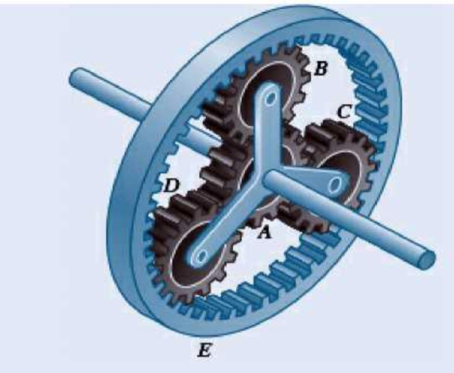
Fig. P6.160
Expert Solution & Answer
Want to see the full answer?
Check out a sample textbook solution
Students have asked these similar questions
In the mechanism shown below, the distributed load W is 300 Nim and the angle 9 is 55, knowing that link AB has 1.5cmx 1.5cm cross-section
Gear A weighs 1.4 lb and has a radius of gyration of 1.2 in.; gear B weighs 5.2 lb and
has a radius of gyration of 2.8 in.; gear C weighs 10.7 lb and has a radius of gyration
of 4.4 in. Knowing a couple M of constant magnitude of 39 lb.in. is applied to gear A,
determine the tangential force that gear B exerts on gear C.
M
A
2 in.
2 in.
4 in.
B
6 in.
Practice Problem 2.4.16: The couple acts on the handlesof a steering mechanism. In the position shown, themoment applied by the couple about the z-axis is zero.Determine the distance b.Use F = 200i − 110j − 80k kN.
Chapter 6 Solutions
Connect 1 Semester Access Card for Vector Mechanics for Engineers: Statics and Dynamics
Ch. 6.1 - 6.1 through 6.8 Using the method of joints,...Ch. 6.1 - 6.1 through 6.8 Using the method of joints,...Ch. 6.1 - Prob. 6.3PCh. 6.1 - 6.1 through 6.8 Using the method of joints,...Ch. 6.1 - Prob. 6.5PCh. 6.1 - Using the method of joints, determine the force in...Ch. 6.1 - 6.1 through 6.8 Using the method of joints,...Ch. 6.1 - Prob. 6.8PCh. 6.1 - 6.9 and 6.10 Determine the force in each member of...Ch. 6.1 - Prob. 6.10P
Ch. 6.1 - Determine the force in each member of the Gambrel...Ch. 6.1 - Determine the force in each member of the Howe...Ch. 6.1 - Using the method of joints, determine the force in...Ch. 6.1 - 6.14 Determine the force in each member of the...Ch. 6.1 - Determine the force in each member of the Warren...Ch. 6.1 - Solve Problem 6.15 assuming that the load applied...Ch. 6.1 - Determine the force in each member of the Pratt...Ch. 6.1 - The truss shown is one of several supporting an...Ch. 6.1 - Determine the force in each member of the Pratt...Ch. 6.1 - Prob. 6.20PCh. 6.1 - Determine the force in each of the members located...Ch. 6.1 - Determine the force in member DE and in each of...Ch. 6.1 - Determine the force in each of the members located...Ch. 6.1 - The portion of truss shown represents the upper...Ch. 6.1 - For the tower and loading of Prob. 6.24 and...Ch. 6.1 - Solve Problem 6.24 assuming that the cables...Ch. 6.1 - Determine the force in each member of the truss...Ch. 6.1 - Determine the force in each member of the truss...Ch. 6.1 - 6.29 Determine whether the trusses of Probs....Ch. 6.1 - 6.30 Determine whether the trusses of Probs....Ch. 6.1 - Prob. 6.31PCh. 6.1 - Prob. 6.32PCh. 6.1 - For the given loading, determine the zero-force...Ch. 6.1 - Prob. 6.34PCh. 6.1 - Prob. 6.35PCh. 6.1 - Prob. 6.36PCh. 6.1 - The truss shown consists of six members and is...Ch. 6.1 - The truss shown consists of nine members and is...Ch. 6.1 - The truss shown consists of nine members and is...Ch. 6.1 - Solve Prob. 6.39 for P = 0 and Q = (900 N)k. 6.39...Ch. 6.1 - The truss shown consists of 18 members and is...Ch. 6.1 - The truss shown consists of 18 members and is...Ch. 6.2 - 6.43 A Mansard roof truss is loaded as shown....Ch. 6.2 - 6.44 A Mansard roof truss is loaded as shown....Ch. 6.2 - Determine the force in members BD and CD of the...Ch. 6.2 - Determine the force in members DF and DG of the...Ch. 6.2 - Prob. 6.47PCh. 6.2 - Prob. 6.48PCh. 6.2 - Determine the force in members CD and DF of the...Ch. 6.2 - Determine the force in members CE and EF of the...Ch. 6.2 - Determine the force in members DE and DF of the...Ch. 6.2 - Prob. 6.52PCh. 6.2 - Determine the force in members DF and DE of the...Ch. 6.2 - Prob. 6.54PCh. 6.2 - Prob. 6.55PCh. 6.2 - 6.56 A monosloped roof truss is loaded as shown....Ch. 6.2 - A Howe scissors roof truss is loaded as shown....Ch. 6.2 - A Howe scissors roof truss is loaded as shown....Ch. 6.2 - Determine the force in members AD, CD, and CE of...Ch. 6.2 - Determine the force in members DG, FG, and FH of...Ch. 6.2 - 6.61 Determine the force in members DG and FI of...Ch. 6.2 - Prob. 6.62PCh. 6.2 - Prob. 6.63PCh. 6.2 - Prob. 6.64PCh. 6.2 - The diagonal members in the center panels of the...Ch. 6.2 - The diagonal members in the center panels of the...Ch. 6.2 - Prob. 6.67PCh. 6.2 - Prob. 6.68PCh. 6.2 - Classify each of the structures shown as...Ch. 6.2 - Classify each of the structures shown as...Ch. 6.2 - Prob. 6.71PCh. 6.2 - 6.70 through 6.74 classify as determinate or...Ch. 6.2 - 6.70 through 6.74 classify as determinate or...Ch. 6.2 - 6.70 through 6.74 classify as determinate or...Ch. 6.3 - For the frame and loading shown, draw the...Ch. 6.3 - For the frame and loading shown, draw the...Ch. 6.3 - Draw the free-body diagram(s) needed to determine...Ch. 6.3 - Knowing that the pulley has a radius of 0.5 m,...Ch. 6.3 - 6.75 and 6.76 Determine the force in member BD and...Ch. 6.3 - 6.75 and 6.76 Determine the force in member BD and...Ch. 6.3 - For the frame and loading shown, determine the...Ch. 6.3 - Determine the components of all forces acting on...Ch. 6.3 - Prob. 6.79PCh. 6.3 - Prob. 6.80PCh. 6.3 - Determine the components of all forces acting on...Ch. 6.3 - Determine the components of all forces acting on...Ch. 6.3 - Determine the components of the reactions at A and...Ch. 6.3 - Determine the components of the reactions at D and...Ch. 6.3 - Determine the components of the reactions at A and...Ch. 6.3 - Determine the components of the reactions at A and...Ch. 6.3 - 6.87 Determine the components of the reactions at...Ch. 6.3 - The 48-lb load can be moved along the line of...Ch. 6.3 - The 48-lb load is removed and a 288-lb in....Ch. 6.3 - (a) Show that, when a frame supports a pulley at...Ch. 6.3 - Knowing that each pulley has a radius of 250 mm,...Ch. 6.3 - Knowing that the pulley has a radius of 75 mm,...Ch. 6.3 - Prob. 6.93PCh. 6.3 - Prob. 6.94PCh. 6.3 - Prob. 6.95PCh. 6.3 - Prob. 6.96PCh. 6.3 - Prob. 6.97PCh. 6.3 - Prob. 6.98PCh. 6.3 - Knowing that P = 90 lb and Q = 60 lb, determine...Ch. 6.3 - Knowing that P = 90 lb and Q = 60 lb, determine...Ch. 6.3 - For the frame and loading shown, determine the...Ch. 6.3 - For the frame and loading shown, determine the...Ch. 6.3 - Prob. 6.103PCh. 6.3 - 6.104 Solve Prob. 6.103 assuming that the 360-lb...Ch. 6.3 - For the frame and loading shown, determine the...Ch. 6.3 - Prob. 6.106PCh. 6.3 - The axis of the three-hinge arch ABC is a parabola...Ch. 6.3 - The axis of the three-hinge arch ABC is a parabola...Ch. 6.3 - Prob. 6.109PCh. 6.3 - Prob. 6.110PCh. 6.3 - 6.111, 6.112, and 6.113 Members ABC and CDE are...Ch. 6.3 - Prob. 6.112PCh. 6.3 - 6.111, 6.112, and 6.113 Members ABC and CDE are...Ch. 6.3 - Prob. 6.114PCh. 6.3 - Solve Prob. 6.112 assuming that the force P is...Ch. 6.3 - Prob. 6.116PCh. 6.3 - Prob. 6.117PCh. 6.3 - Prob. 6.118PCh. 6.3 - 6.119 through 6.121 Each of the frames shown...Ch. 6.3 - 6.119 through 6.121 Each of the frames shown...Ch. 6.3 - 6.119 through 6.121 Each of the frames shown...Ch. 6.4 - An 84-lb force is applied to the toggle vise at C....Ch. 6.4 - For the system and loading shown, draw the...Ch. 6.4 - Prob. 6.7FBPCh. 6.4 - The position of member ABC is controlled by the...Ch. 6.4 - The shear shown is used to cut and trim...Ch. 6.4 - A 100-lb force directed vertically downward is...Ch. 6.4 - Prob. 6.124PCh. 6.4 - The control rod CE passes through a horizontal...Ch. 6.4 - Solve Prob. 6.125 when (a) = 0, (b) = 6. Fig....Ch. 6.4 - The press shown is used to emboss a small seal at...Ch. 6.4 - The press shown is used to emboss a small seal at...Ch. 6.4 - Prob. 6.129PCh. 6.4 - The pin at B is attached to member ABC and can...Ch. 6.4 - Arm ABC is connected by pins to a collar at B and...Ch. 6.4 - Arm ABC is connected by pins to a collar at B and...Ch. 6.4 - The Whitworth mechanism shown is used to produce a...Ch. 6.4 - Prob. 6.134PCh. 6.4 - Prob. 6.135PCh. 6.4 - Prob. 6.136PCh. 6.4 - 6.137 and 6.138 Rod CD is attached to the collar D...Ch. 6.4 - 6.137 and 6.138 Rod CD is attached to the collar D...Ch. 6.4 - Two hydraulic cylinders control the position of...Ch. 6.4 - Prob. 6.140PCh. 6.4 - Prob. 6.141PCh. 6.4 - Prob. 6.142PCh. 6.4 - Prob. 6.143PCh. 6.4 - Prob. 6.144PCh. 6.4 - The pliers shown are used to grip a...Ch. 6.4 - 6.146 Determine the magnitude of the gripping...Ch. 6.4 - In using the bolt cutter shown, a worker applies...Ch. 6.4 - Prob. 6.148PCh. 6.4 - Prob. 6.149PCh. 6.4 - and 6.150 Determine the force P that must be...Ch. 6.4 - Prob. 6.151PCh. 6.4 - Prob. 6.152PCh. 6.4 - 6.153 The motion of the bucket of the front-end...Ch. 6.4 - Prob. 6.154PCh. 6.4 - The telescoping arm ABC is used to provide an...Ch. 6.4 - The telescoping arm ABC of Prob. 6.155 can be...Ch. 6.4 - The motion of the backhoe bucket shown is...Ch. 6.4 - Prob. 6.158PCh. 6.4 - Prob. 6.159PCh. 6.4 - In the planetary gear system shown, the radius of...Ch. 6.4 - Two shafts AC and CF, which lie in the vertical xy...Ch. 6.4 - Two shafts AC and CF, which lie in the vertical xy...Ch. 6.4 - The large mechanical tongs shown are used to grab...Ch. 6 - Using the method of joints, determine the force in...Ch. 6 - Using the method of joints, determine the force in...Ch. 6 - A stadium roof truss is loaded as shown. Determine...Ch. 6 - A stadium roof truss is loaded as shown. Determine...Ch. 6 - Determine the components of all forces acting on...Ch. 6 - Prob. 6.169RPCh. 6 - Knowing that the pulley has a radius of 50 mm,...Ch. 6 - For the frame and loading shown, determine the...Ch. 6 - For the frame and loading shown, determine the...Ch. 6 - Water pressure in the supply system exerts a...Ch. 6 - A couple M with a magnitude of 1.5 kNm is applied...Ch. 6 - Prob. 6.175RP
Knowledge Booster


Learn more about
Need a deep-dive on the concept behind this application? Look no further. Learn more about this topic, mechanical-engineering and related others by exploring similar questions and additional content below.Similar questions
- QUESTION 4 The two shafts of a speed-reducer unit are subjected to couples of magnitude M1 = 10 Ib-ft and M2 = 5 lb-ft, respectively. Replace the two couples with a single equivalent couple, specifying its magnitude and the direction of its axis. O M = 10.18 Ib-ft, 0x = 26.57, 0y = 90.00, 02 = 63.43 O M = 11.18 Ib-ft, 0x = 26.57, 0y = 90.00, 02 = 63.4 O M = 12.18 Ib-ft, 6x = 26.57, 0y = 90.00, 02 = 63.43 O M = 10.18 Ib-ft, 6x = 63.43, 0y = 90.00, 02 = 26.57 O M = 11.18 Ib-ft, Ox = 63.43, 6y = 90.00, 02 = 26.57 O M = 12.18 Ib-ft, 8x = 63.43, 0y = 90.00, 02 = 26.57arrow_forwardA machine component is subjected to the forces and couples shown. The component is to be held in place by a single rivet that can resist a force but not a couple. For P hole if it is to be located (a) on line FG, (b) on line GH. 0, determine the location of the rivet '120 N 240 mm 200 N 70° 15° E 50 mm 42 N-m 80 N 520 mm 40 N-m 180 mm В 50 mm 50 mm → 640 mmarrow_forward4 من إجمالي 4 H.W.4 In the design of a control mechanism, it is determined that rod AB transmits a 260-N force P to the crank BC. Determine the x and y scalar components of P. P= 260 N 5 12 B y 30°arrow_forward
- 4. The rigid link is supported by a pin at A, a steel wire BC having an unstretched length of 300 mm and cross-sectional area of 20 mm², and a short aluminum block having a length of 100 mm under no load and cross-sectional area of 40 mm². If the link is subjected to a vertical force of 550 N as shown, determine the force in wire BC and the aluminum block, and the rotation of the link about pin A. Est = 200 GPa, EA = 70 GPa. 300 mm B 200 mm 550N 250mm D A 250 mm 100 mmarrow_forwardThe pipe ABCDE is supported by ball-and-socket joints at A and D and by cable ECF that passes through a ring C with negligible friction and is attached to hooks at E and F. Knowing that the frame supports a uniformly distributed load of 1500 N/m along segment AB, do the following.1) Shows the correct vector representation of the resultant of the two tension forces acting at ring C. Note that T_CF = T_CE = T2) Explain along which line/axis you can sum moments to generate an equilibrium equation with only the magnitude of the tension force as the unknown. Explain your choice.3) Find the magnitude of the tension force.arrow_forwardA couple acts on the gear teeth as shown in the figure below. Replace it by an equivalent couple having a pair of forces that act through (a) points A and B.arrow_forward
- Q6 A machine component is subjected to the forces and couples shown. The component is to be held in place by a single rivet that can resist a force but not a couple. The location of the rivet hole on line FG and line GH is... 120 N 240 mm 200 N 70° 15 H 50 mm 42 Nm 180 N 520 mm C 60 N 180 mm F |B -50 mm 40 Nm iG A 50 mm 640 mmarrow_forwardTwo identical ball bearings Pand Qare operating at loads 30 kN and 45 kN respectively The ratio of the life of bearing P to the life of bearing Q is....arrow_forwardExercises: 1. The box wrench in Fig. 99 is used to tighten the bolt at A. If the wrench does not turn when the load is applied to the handle, determine the torque or moment applied to the bolt and the force of the wrench on the bolt. 300 mm 400 mm 60° 12 52'N 30 N Fig. 99 2. Determine the horizontal and vertical 750 lb components of reaction on the member at the pin A, and the normal reaction at the roller B in Fig. 100. 3 ft 3 ft 2 ft 30 Fig. 100 3. The uniform smooth rod shown in Fig. 101 is subjected to a force and couple moment. If the rod is supported at A by a smooth wall and at B and C either at the top or bottom by rollers, determine the reactions at these supports. Neglect the weight of the rod. 2 m 4 m 4000 N m 2m B 300 N 2 m 30° Fig. 101 4. Determine the support reactions on the member in Fig. 102. The collar at A is fixed to the member and can slide vertically along the vertical shaft. 900 N 1.5 m- 1.5 m 1 m 45° 500 N marrow_forward
- Determine the magnitude and direction of the couple moment actingon the gear shown.arrow_forwardSolve Prob. 4.91, assuming that the pulley rotates at a constant rate and that TB = 104 N, T'B = 84 N, and TC= 175 N.(Reference to Problem 4.91):Two transmission belts pass over a double-sheaved pulley that is attached to an axle supported by bearings at A and D . The radius of the inner sheave is 125 mm and the radius of the outer sheave is 250 mm. Knowing that when the system is at rest, the tension is 90 N in both portions of belt B and 150 N in both portions of belt C, determine the reactions at A and D . Assume that the bearing at D does not exert any axial thrust.arrow_forwardTwo rods are connected by a slider block as shown. Given: MB= 250 lb-in. MA MB 25° 15 in. A |B 15 in.- Draw the free-body diagram needed to determine the couple MA required to hold the system in equilibrium.arrow_forward
arrow_back_ios
SEE MORE QUESTIONS
arrow_forward_ios
Recommended textbooks for you
 Elements Of ElectromagneticsMechanical EngineeringISBN:9780190698614Author:Sadiku, Matthew N. O.Publisher:Oxford University Press
 Mechanics of Materials (10th Edition)Mechanical EngineeringISBN:9780134319650Author:Russell C. HibbelerPublisher:PEARSON
 Thermodynamics: An Engineering ApproachMechanical EngineeringISBN:9781259822674Author:Yunus A. Cengel Dr., Michael A. BolesPublisher:McGraw-Hill Education
 Control Systems EngineeringMechanical EngineeringISBN:9781118170519Author:Norman S. NisePublisher:WILEY
 Mechanics of Materials (MindTap Course List)Mechanical EngineeringISBN:9781337093347Author:Barry J. Goodno, James M. GerePublisher:Cengage Learning
 Engineering Mechanics: StaticsMechanical EngineeringISBN:9781118807330Author:James L. Meriam, L. G. Kraige, J. N. BoltonPublisher:WILEY
Elements Of Electromagnetics
Mechanical Engineering
ISBN:9780190698614
Author:Sadiku, Matthew N. O.
Publisher:Oxford University Press
Mechanics of Materials (10th Edition)
Mechanical Engineering
ISBN:9780134319650
Author:Russell C. Hibbeler
Publisher:PEARSON
Thermodynamics: An Engineering Approach
Mechanical Engineering
ISBN:9781259822674
Author:Yunus A. Cengel Dr., Michael A. Boles
Publisher:McGraw-Hill Education
Control Systems Engineering
Mechanical Engineering
ISBN:9781118170519
Author:Norman S. Nise
Publisher:WILEY
Mechanics of Materials (MindTap Course List)
Mechanical Engineering
ISBN:9781337093347
Author:Barry J. Goodno, James M. Gere
Publisher:Cengage Learning
Engineering Mechanics: Statics
Mechanical Engineering
ISBN:9781118807330
Author:James L. Meriam, L. G. Kraige, J. N. Bolton
Publisher:WILEY
Power Transmission; Author: Terry Brown Mechanical Engineering;https://www.youtube.com/watch?v=YVm4LNVp1vA;License: Standard Youtube License