
Videos
A timber beam AB of Length L and rectangular cross section carries a uniformly distributed load w and is supported as shown. (a) Show that the ratio τm/σm of the maximum values of the shearing and normal stresses in the beam is equal to 2h/L, where h and L are, respectively, the depth and the length of the beam. (b) Determine the depth h and the width b of the beam, knowing that L = 5 m, w = 8 kN/m, τm = 1.08 MPa, and σm = 12 MPa.
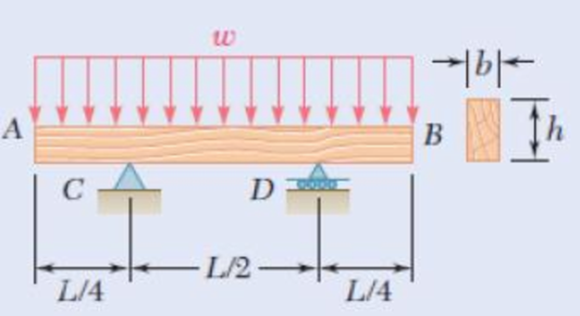
Fig. P6.20
(a)
To show that: The ratio
Answer to Problem 20P
The ratio
Explanation of Solution
Given information:
The length of the beam AB is L.
The depth of the beam is h.
Calculation:
Calculate the area of the cross section as shown below.
Here, b is the width of the beam and h is the depth of the beam.
Calculate the section modulus of the cross section as shown below.
Due to the symmetry of the beam reaction at supports C and D are Equal.
Calculate the shear force as shown below.
Shear force at A,
Shear force at A right,
Shear force at C,
Shear force at D,
Shear force at B,
Calculate the bending moment as shown below.
BM at A,
BM at C,
BM at D,
BM at B,
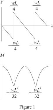
Sketch the shear force and bending moment diagram as shown in Figure 1.
Calculate the maximum shear stress as shown below.
Substitute
Calculate the maximum normal stress as shown below.
Substitute
Calculate the ratio
Therefore, the ratio
(b)
The depth and width of the beam.
Answer to Problem 20P
The depth of the beam is
The width of the beam is
Explanation of Solution
Given information:
The length (L) of the beam is
The load is
The maximum shear stress is
The maximum normal stress is
Calculation:
Refer to part (a).
Calculate the depth of the beam as shown below.
Substitute
Hence, the depth of the beam is
Calculate the width of the beam as shown below.
Substitute
Therefore, the width of the beam is
Want to see more full solutions like this?
Chapter 6 Solutions
EBK MECHANICS OF MATERIALS


- Homework A timber beam AB of length L and rectangular cross section carries a single concentrated load P at its midpoint C. (a) Show that the ratio Tm/0, of the maximum values of the shearing and normal stresses in the beam is equal to h/2L, where h and L are, respectively, the depth and the length of the beam. (b) Determine the depth h and the width b of the beam, knowing that L = 2 m, P = 40 kN, 7,m = 960 kPa, and om 12 MPa. %3D L/2- - L/2 16|- Вarrow_forward2. Link AB, of width b 5 50 mm and thickness t 5 6 mm, is used to support the end of a horizontal beam. Knowing that the average normal stress in the link is 2140 MPa, and that the average shearing stress in each of the two pins is 80 MPa, determine (a) the diameter d of the pins, (b) the average bearing stress in the link.arrow_forwardA steel bar and an aluminum bar are bonded together to form the composite beam shown. The modulus of elasticity for aluminum is 70 GPa and for steel is 200 GPa. Knowing that the beam is bent about a horizontal axis by a couple of moment M= 1500 N·m, determine the maximum stress in (a) the aluminum, (b) the steel.arrow_forward
- An annular washer distributes the load P applied to a steel rod to a timber support. The rod's diameter is 22 mm, and the washer's inner diameter is 25 mm, which is larger than the hole's permissible outer diameter. Knowing that the axial normal stress in the steel rod is 35 MPa and the average bearing stress between the washer and the timber must not exceed 5 MPa, examine the smallest allowed outer diameter, d, of the washer. %3D %3D +22 mm P Figure 4arrow_forwardTwo wooden members of uniform rectangular cross section of sides a = 100 mm and b = 60 mm are joined by a simple glued joint as shown. Knowing that the ultimate stresses for the joint are σU =1.26 MPa in tension and τU = 1.50 MPa in shear and that P =6 kN, determine the factor of safety for the joint when (a) α =20°,(b) α =35°, (c) α =45°. For each of these values of α, also determine whether the joint will fail in tension or in shear if P is increased until rupture occurs.arrow_forward2.5m 3.5m 4.0m- The 4-mm diameter cable BC is made of steel with E = 200 GPa. Knowing that the maximum stress in the cable must not exceed 190 MPa and that the elongation of the cable must not exceed 6mm, find the maximum load P that can be applied as shown.arrow_forward
- 5. The load P applied to a steel rod is distributed to a timber support by an annular washer. The diameter of the rod is 22 mm and the inner diameter of the washer is 25 mm, which is slightly larger than the diameter of the hole. Determine the smallest allowable outer diameter d of the washer, knowing that the axial normal stress in the steel rod is 35 MPa and the average bearing stress between the washer and the timber must not exceed 5 MPa. - 22 mmarrow_forwardTwo wooden boards, measuring 15 mm thick and 225 mm wide, are joined by the socket joint shown. Knowing that the wood employed will break when the average shear stress reaches 10 MPa, determine the intensity P of the axial force that will break the joint.arrow_forward+3 in- B in. A vertical force P of magnitude 20 kips is applied at point C located on the axis of symmetry of the cross section of a short column. Knowing that y = 5 in., determine (a) the stress at point A, (b) the stress at point B, (c) the location of the neutral axis. 2 in. 4 in. A 2 in. 2 in. 1 in. (a) (b)arrow_forward
- The rigid beam BC is supported by rods (1) and (2). The cross-sectional area of rod (1) is 7 mm2. The cross-sectional area of rod (2) is 18 mm2. For a uniformly distributed load of w = 2.5 kN/m, determine the length a so that the normal stress is the same in each rod. Assume L = 3.10 m. D (1) B |C aarrow_forwardA laminated wood beam consists of eight 2.25 in. × 5.00-in. planks glued together to form a section b = 5.00 in. wide by d = 18 in. deep, as shown and w = 663.2 lb/ft. If the allowable strength of the glue in shear is 105 psi, Determine: (c) the maximum tension bending stress in the beam when the load of part (a) is applied. [σ = 1330 psi]arrow_forwardTwo cylindrical rods, one of steel and the other of brass, are joined at C and restrained by rigid supports at A and E. The steel rod has a length of 300 mm while the brass rod has a length of 200 mm. The diameters of the rods are shown in the figure below. A force of 60 kN is applied at point B of the steel segment. For the loading shown and knowing that modulus of elasticity values for steel and brass are respectively Es = 200 GPa and Eb = 105 GPa, determine a.) The reactions at A and E: RA and RE. b.) The deflection of point C from its original location. how to doarrow_forward
 Elements Of ElectromagneticsMechanical EngineeringISBN:9780190698614Author:Sadiku, Matthew N. O.Publisher:Oxford University Press
 Mechanics of Materials (10th Edition)Mechanical EngineeringISBN:9780134319650Author:Russell C. HibbelerPublisher:PEARSON
 Thermodynamics: An Engineering ApproachMechanical EngineeringISBN:9781259822674Author:Yunus A. Cengel Dr., Michael A. BolesPublisher:McGraw-Hill Education
 Control Systems EngineeringMechanical EngineeringISBN:9781118170519Author:Norman S. NisePublisher:WILEY
 Mechanics of Materials (MindTap Course List)Mechanical EngineeringISBN:9781337093347Author:Barry J. Goodno, James M. GerePublisher:Cengage Learning
 Engineering Mechanics: StaticsMechanical EngineeringISBN:9781118807330Author:James L. Meriam, L. G. Kraige, J. N. BoltonPublisher:WILEY