
Mechanics of Materials (MindTap Course List)
9th Edition
ISBN: 9781337093347
Author: Barry J. Goodno, James M. Gere
Publisher: Cengage Learning
expand_more
expand_more
format_list_bulleted
Videos
Textbook Question
Chapter 6, Problem 6.9.13P
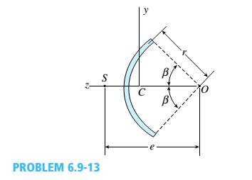
A cross section in the shape of a circular arc of constant thickness is shown in the figure. Derive the following formula for the distance e from the center of the arc to the shear center S:
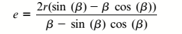
in which ß is in radians. Also, plot a graph showing how the distance e varies as ß varies from 0 to tl
Expert Solution & Answer

Trending nowThis is a popular solution!

Students have asked these similar questions
Draw the complete shearing force and bending moment diagram for the beam shown in figure (2).
Use the last TWO digit of your ID Number for the missing force (F). 75
4 m
F KN/m
4 m
12 m
Figure (2)
Q/ For the beams and loading shown below.
A-Draw the shear force and bending-moment diagrams.
B- Determine the equations of the shear force and bending-moment curves for the segments CD
in Figure 2
C- Compute the bending stress at point (a) on section C.
D- Determine the values and locations of the maximum tensile and compression bending
stresses.
Figure (2)
R
Point a
Radius of hole:
40kN
0.5m
30
20KN/m
0.7m
A
B
D
|B
1m
Im
3m
Radius = R= 100 mm
The figure shows a square element with sides parallel to the x y axes. The axis is horizontally rightward. The y axis is vertically upward. Each side of the square is accompanied by normal and shear stress vectors. Normal vertical stress of 100 megapascals is inward. Normal horizontal stress of 30 megapascals is outward. Shear stress vectors of 50 megapascals are directed toward the upper right and lower left vertices of the square.
Chapter 6 Solutions
Mechanics of Materials (MindTap Course List)
Ch. 6 - A composite beam is constructed using a steel...Ch. 6 - A wood beam is strengthened using two steel plates...Ch. 6 - A composite beam consisting of fiberglass faces...Ch. 6 - A wood beam with cross-sectional dimensions 200 mm...Ch. 6 - A hollow box beam is constructed with webs of...Ch. 6 - A r o lukI f/frm f «m t ub e of ou t sid e d ia...Ch. 6 - A beam with a guided support and 10-ft span...Ch. 6 - A plastic-lined steel pipe has the cross-sectional...Ch. 6 - The cross section of a sand wie h beam consisting...Ch. 6 - The cross section of a sandwich beam consisting of...
Ch. 6 - A bimetallic beam used in a temperature-control...Ch. 6 - A simply supported composite beam 3 m long carries...Ch. 6 - A simply supported wooden I-beam with a 12-ft span...Ch. 6 - -14 A simply supported composite beam with a 3.6 m...Ch. 6 - -15 A composite beam is constructed froma wood...Ch. 6 - A wood beam in a historic theater is reinforced...Ch. 6 - Repeat Problem 6.2-1 but now assume that the steel...Ch. 6 - Repeat Problem 6.2-17 but now use a...Ch. 6 - A sandwich beam having steel faces enclosing a...Ch. 6 - A wood beam 8 in. wide and 12 in. deep (nominal...Ch. 6 - A simple beam of span length 3.2 m carries a...Ch. 6 - A simple beam that is 18 ft long supports a...Ch. 6 - The composite beam shown in the figure is simply...Ch. 6 - The cross section of a beam made of thin strips of...Ch. 6 - Consider the preceding problem if the beam has...Ch. 6 - A simple beam thai is IS ft long supports a...Ch. 6 - The cross section of a composite beam made of...Ch. 6 - A beam is constructed of two angle sections, each...Ch. 6 - The cross section of a bimetallic strip is shown...Ch. 6 - A W 12 x 50 steel wide-flange beam and a segment...Ch. 6 - A reinforced concrete beam (see figure) is acted...Ch. 6 - A reinforced concrete T-beam (see figure) is acted...Ch. 6 - A reinforced concrete slab (see figure) is...Ch. 6 - A wood beam reinforced using two channels is...Ch. 6 - A wood beam reinforced by an aluminum channel...Ch. 6 - A beam with a rectangular cross section supports...Ch. 6 - A wood beam with a rectangular cross section (see...Ch. 6 - Solve the preceding problem for the following...Ch. 6 - A simply supported wide-flange beam of span length...Ch. 6 - Solve the preceding problem using the fol...Ch. 6 - A wood cantilever beam with a rectangular cross...Ch. 6 - Solve the preceding problem for a cantilever beam...Ch. 6 - A 2-m-long cantilever beam is constructed using a...Ch. 6 - A wood beam AB with a rectangular cross section (4...Ch. 6 - A steel beam of I-section (see figure) is simply...Ch. 6 - A cantilever beam with a wide-flange cross section...Ch. 6 - Solve the preceding problem using a W 310 x 129...Ch. 6 - A cantilever beam of W 12 × 14 section and length...Ch. 6 - A cantilever beam built up from two channel...Ch. 6 - A built-Lip I-section steel beam with channels...Ch. 6 - Repeat Problem 6.4-14 but use the configuration of...Ch. 6 - A beam with a channel section is subjected to a...Ch. 6 - A beam with a channel section is subjected to a...Ch. 6 - An angle section with equal legs is subjected to a...Ch. 6 - An angle section with equal legs is subjected to a...Ch. 6 - A beam made up all woun equal leg angles is...Ch. 6 - The Z-section of Example D-7 is subjected to M = 5...Ch. 6 - The cross section of a steel beam is constructed...Ch. 6 - The cross section of a steel beam is shown in the...Ch. 6 - A beam with a semicircular cross section of radius...Ch. 6 - .10 A built-up bourn supporting a condominium...Ch. 6 - Asteelpost (E = 30 × 106 psi) having thickness t =...Ch. 6 - A C 200 x 17.1 channel section has an angle with...Ch. 6 - A cold-formed steel section is made by folding a...Ch. 6 - A simple beam with a W 10 x 30 wide-flange cross...Ch. 6 - Solve the preceding problem for a W 250 × 44.8...Ch. 6 - A beam of wide-flange shape, W 8 x 28, has the...Ch. 6 - Solve the preceding problem for a W 200 × 41,7...Ch. 6 - Calculate the distance e from the cent crime of...Ch. 6 - Calculate the distance e from the centerline of...Ch. 6 - The cross section of an unbalanced wide-flange...Ch. 6 - The cross section of an unbalanced wide-flange...Ch. 6 - The cross section of a channel beam with double...Ch. 6 - The cross section of a slit circular tube of...Ch. 6 - The cross section of a slit square tube of...Ch. 6 - The cross section of a slit rectangular tube of...Ch. 6 - A U-shaped cross section of constant thickness is...Ch. 6 - Derive the following formula for the distance e...Ch. 6 - Derive the following formula for the distance e...Ch. 6 - The cross section of a sign post of constant...Ch. 6 - A cross section in the shape of a circular arc of...Ch. 6 - Determine the shape factor f for a cross section...Ch. 6 - (a) Determine the shape factor/for a hollow...Ch. 6 - A propped cantilever beam of length L = 54 in....Ch. 6 - A steel beam of rectangular cross section is 40 mm...Ch. 6 - .5 Calculate the shape factor j for the...Ch. 6 - Solve the preceding problem for a wide-flange beam...Ch. 6 - Determine the plastic modulus Z and shape...Ch. 6 - Prob. 6.10.8PCh. 6 - Prob. 6.10.9PCh. 6 - Prob. 6.10.10PCh. 6 - A hollow box beam with height h = 16 in,, width h...Ch. 6 - Solve the preceding problem for a box beam with...Ch. 6 - A hollow box beam with height h = 9.5 in., inside...Ch. 6 - Solve the preceding problem for a box beam with...Ch. 6 - The hollow box beam shown in the figure is...Ch. 6 - Prob. 6.10.16PCh. 6 - Prob. 6.10.17PCh. 6 - A singly symmetric beam with a T-section (see...Ch. 6 - A wide-flange beam with an unbalanced cross...Ch. 6 - .20 Determine the plastic moment Mpfor beam having...
Knowledge Booster


Learn more about
Need a deep-dive on the concept behind this application? Look no further. Learn more about this topic, mechanical-engineering and related others by exploring similar questions and additional content below.Similar questions
- The simply supported beam is subjected to the force F = 700 N and the uniform distributed load with intensity w = 150 N/m. Draw the shear force and bending moment diagrams (in your homework documentation) and determine the equations for V(r) and M(x). Take a = 0 at point A. 19 F a Values for dimensions on the figure are given in the following table. Note the figure may not be to scale. Variable Value a 5.2 m 2.6 m 3.12 m Support Reactions The reaction at A is N. The reaction at D is N. Shear Force and Bending Moment Equations In section AB: V(x)= N and M(x)= N-m. In section BC: v(x)- N and M(x)= N-m. In section CD: V(x)- N and M(x)= N-m. Aarrow_forwardFor the simply supported beam subjected to the loading shown, sketch the shear force diagram. Determine the largest magnitude shear force. Let a=13.0 ft, b=4.0 ft, c= 8.0 ft, w = 17 kips/ft and M = 243 kip-ft. Give your answer in kips. Enter a positive number. M B C D aarrow_forwardThe three cross-sections shown in Figure A12 have the same cross-sectional area and are subjected to the same bending moment about their horizontal axis of symmetry. Section (a) is a square section. Sections (b) and (c) are composed of two rectangular sections that are placed loosely next to each other. If a, b and are their respective maximum bending stresses on the three sections, which one of the following relations is correct? 2a 2a 2a 2a a a (a) (b) а) басть сос b) σa=0b < oc α c) ба< Gb = ос d) a= b = 0c Figure A12 (c) To Po a aarrow_forward
- 1. Determine the resultant internal loadings acting on the cross section at B of the pipe shown. End A is subjected to a vertical force P and a horizontal force Q. Use P = 95 N and Q = 75 N. 0.75 m B `0.5 m D. D> P 1.25 m A Determine the internal axial force (in N) in section B. * Your answer Determine the internal shear force (in N) in section B. * Your answerarrow_forwardA force of F = 13 kips is applied as shown in the figure below. If the diameter of the bolt is d = 1.4 inches, find the maximum average shear stress in the bolt. Report your value in units of psi to one decimal place. Farrow_forwardDetermine the axial force, shear force, and bending moment at point J located on member AB of the landing gear of an airplane, as shown in the figure.All distances are in inches.arrow_forward
- Use the diagram shown above. Given: • D₁ = 10 ft . • D₂ = 3 ft A #/ft . W = 100 W-100 Solve for the internal moment at X. D₂ D₁ W X Note: Enter your calculation results without the unit. You'll be asked to specify the unit for your calculation result in the following question. (e.g. if it's positive 100, enter 100, if it's negative 100, enter -100.)arrow_forwardQ4: If the cross section of the beam shown in the figure (3) below has bending stress of 28 MN/m² in the bottom surface, then determine the bending stress in the top surface. 100 mm top 100 mm bottom 25mm 25mm Figure (3) Activate Windows Go to Settings to activate Windoarrow_forwardThe cross section of a slit rectangular tube of constant thickness is shown in the figures. (a) Derive the following formula for the distance e from the centerline of the wall of the tube in the figure part a to the shear center S: (b) Find an expression for e if flanges with the same thickness as that of the tube arc added as shown in figure part b.arrow_forward
- F=30 kN single load, M=34 kN.m moment and w=10 kN/m distributed load are acting on the beam whose loading condition is given in the figure. Point B is located just to the right of the application point of force F and moment M. The length L is also given as L=5 m. According to this; Question1-D) Find the bending moment (MB) at point B. (Write your result in kN.m.) Question1-E) Find the shear force (VC) at point C. (Write your result in kN.)Question1-F) Find the bending moment (MC) at point C. (Write your result in kN.m.)arrow_forward10 in 1 in 1 in V 12 in 1 in 10 in The wide flange beam above is subjected to a vertical internal shear force V, as shown. Note that the diagram is not shown to scale. Which of the following is closest to the moment of inertia (I) that would be used to calculate the shear stresses on the cross-section due to V? 1051 in4 O 777 in4 O 991 in4 805 in4arrow_forwardConsider the circular bent rod with diameter 20 mm. The free-end of the bend is subjected to loads as shown in the figure below. Find the total shear stress, 7 at point p (Hint: includes both torsional shear stress and transverse shear stress) in section a-a in MPn. Enter only numeric value without units upto 1 digit after decimal point, but with correct sign. 200 mm NA 200 mm D. R. Section a-a 400 N 800 Narrow_forward
arrow_back_ios
SEE MORE QUESTIONS
arrow_forward_ios
Recommended textbooks for you
 Mechanics of Materials (MindTap Course List)Mechanical EngineeringISBN:9781337093347Author:Barry J. Goodno, James M. GerePublisher:Cengage Learning
Mechanics of Materials (MindTap Course List)
Mechanical Engineering
ISBN:9781337093347
Author:Barry J. Goodno, James M. Gere
Publisher:Cengage Learning
Unit Conversion the Easy Way (Dimensional Analysis); Author: ketzbook;https://www.youtube.com/watch?v=HRe1mire4Gc;License: Standard YouTube License, CC-BY