
Concept explainers
Videos
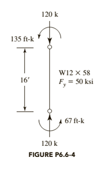
The member shown in Figure P6.6-4 is part of a braced frame. The load and moments are computed from service loads, and bending is about the
a. Use LRFD.
b. Use ASD.

Trending nowThis is a popular solution!

Chapter 6 Solutions
Steel Design (Activate Learning with these NEW titles from Engineering!)


- For the truss shown and loading, determine the axial stress in member BG in ksi. Use two decimal places. Express your answer in absolute value. Assume the sectional areas of the following: Top and bottom members = 1.80 in? Web members = 0.90 in? H 6 ft B 20 kip 40 kip 6 ft @ 4 = 24 ftarrow_forwardBeam AB is supported as shown in the figure. Tie rod (1) is attached at B and C with double shear pin connections, while the pin at A is attached with a single shear connection. The pins at A, B, and C each have an ultimate shear strength of 57 ksi, and tie rod (1) has a yield strength of 33 ksi. A concentrated load of P = 14 kips is applied to the beam as shown. A factor of safety of 2.4 is required for all components. Determine: (a) the minimum required diameter for tie rod (1). (b) the minimum required diameter for the double shear pins at B and C. (c) the minimum required diameter for the single shear pin at A. 6.7 8 in. 3.8ft (2) 8.5ftarrow_forwardConsider the truss shown in (Figure 1). Set P₁ = 8 kN, P₂ = 10 kN, and P3 = 6 kN. Figure E ZA B C 3m P₁ P3 3m < 1 of 1 P₂ -3m- 3m D. ✓ Correct ▼ Part D Determine the force in member BF of the truss and state if this member is in tension or compression. Express your answer to three significant figures and include the appropriate units. Enter negative value in the case of compression and positive value in the case of tension. FBF = 7.67 HA kN Submit Previous Answers Request Answer ? Review * Incorrect; Try Again; 5 attempts remainingarrow_forward
- A simply supported planar truss is subjected to point loads at joint B and D as shown in Figure 2. Based on the given truss, answer the following questions: a. Identify zero force member in the truss (if any). Provide the justification for your answer with the calculation. b. Using any suitable method, find force in members BC, HC and HG c. Is the force in member AH is similar in member FE? Provide your reason with the calculation. 5 kN 4 kN 13.27m A E H G F 5m 5m 5m - 5marrow_forwardProblem 1 (.:..D. For the given truss below, answer the questions. A = 1.5 in? and E = 29,000 ksi 2 k 2 k 2 k D E, F for all members: Sthe virtual loau nee 6 ft calcup B ma hertical disnenament of 8 ft 8 ft Amsng a unTZ OMULmer od Show the virtual load on the answer sheet to calculate the vertical displacement of joint E (Ag) using Castigliano's theorem (mark the magnitude of the load). (d) | Determine the vertical displacement of joint E (Ag) using Castigliano's theorem.arrow_forwardUse Virtual Work Method to answer the questions below considering the truss shown. Use the cross-sectional areas (A, in?) specified in the figure, E- 30 ksi and a - 20 x 10/ °F. "a" is hinge supported and "c" is roller supported. 80 (7.5) 10 (7.5) (4) (4) 20 20 1. Select the answer that most nearly gives the axial force on member cb from the real structure in kips. Put (-) negative sign if its under compression. I Select] 2. Select the answer that most nearly gives the absolute value of axial force on member ab from the virtual structure for horizontal displacement of joint d. I Select | 3. Select the answer that most nearly gives the absolute value of axial force on member bd from the virtual structure for horizontal displacement of joint d. I Select | 4. Select the answer that most nearly gives the horizontal displacement of joint d in inches due to external force only. Put (-) negative sign if its to the left. I Select ] 5. Select the answer that most nearly gives the horizontal…arrow_forward
- Problem 2: Determine the forces in all diagonal and horizontal members of the truss shown below using the method of sections. Determine the force in all vertical members using the method of joints. Hint, the structure is symmetric. The distributed load is transferred to the truss from the roof purlins. State whether the members are tension or compression. Summarize your results on a sketch of the truss. 2.5 k/ft H M K 12 ft A G B C D F 6 @ 12 ft = 72 ftarrow_forwardFor the truss shown and loading, determine the axial stress in member BH in ksi. Use two decimal places. Express your answer in absolute value. Assume the sectional areas of the following: Top and bottom members = 1.80 in² Web members = 0.90 in² B 20 kip с 40 kip 6 ft @ 4 = 24 ft D 6 ftarrow_forwardThe steel is supported by the steel tie rod in AB beam B. Steel connection tension rod is placed 2 meters to the left of B and C sliding bracket is placed and P is loaded between AC It is. By ignoring the weights of beams and connecting rods, they can be determine the largest P load it can carry. The diameter of the BD rod is 16 mm. E = 200GPa I = 150x106mm4arrow_forward
- For the truss shown in Figure 2.3b, determine the force in member DK if x = 5 m, y = 7 m and P = 7.82 kN. Indicate whether the member is in tension or compression. (Note: Use negative sign (-) if the member is in compression.) 7 panels at x m = 7x m В I C D K L y F х М Н P P kN P kNarrow_forwardA cantilever pin jointed frame is shown in figure with four members AB, BC, CD and BD. Determine the magnitude and nature of forces (compressive or tensile) in all the members and tabulate your result. (Use method of joints showing all the steps). B Preform the following: F kN i) Freebody diagram of the frame/ Truss. ii) Determination of forces in all members including nature of forces. Data given : a= 0.4 m , b= 0.5 m, c = 3 m, F= 2 kNarrow_forwardFor the truss shown in Figure 2.3b, determine the force in member DG if x = 5 m, y = 3 m and P = 6 kN. Indicate whether the member is in tension or compression. (Note: Use negative sign (-) if the member is in compression.) 7 panels at x m = 7x m В J C D K E y F A N H G P kN P kNarrow_forward

 Structural Analysis (10th Edition)Civil EngineeringISBN:9780134610672Author:Russell C. HibbelerPublisher:PEARSON
 Principles of Foundation Engineering (MindTap Cou...Civil EngineeringISBN:9781337705028Author:Braja M. Das, Nagaratnam SivakuganPublisher:Cengage Learning
 Fundamentals of Structural AnalysisCivil EngineeringISBN:9780073398006Author:Kenneth M. Leet Emeritus, Chia-Ming Uang, Joel LanningPublisher:McGraw-Hill Education
 Traffic and Highway EngineeringCivil EngineeringISBN:9781305156241Author:Garber, Nicholas J.Publisher:Cengage Learning