Concept explainers
6-37* to 6-46* For the problem specified in the table, build upon the results of the original problem to determine the minimum factor of safety for fatigue based on infinite life, using the modified Goodman criterion. The shaft rotates at a constant speed, has a constant diameter, and is made from cold-drawn AISI 1018 steel.
| Problem Number | Original Problem, Page Number |
| 6-43* | 3–74, 152 |
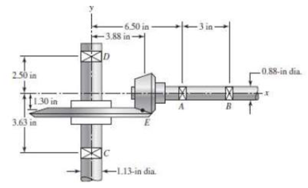
3-74* In the figure, shaft AB transmits power to shaft CD through a set of bevel gears contacting at point E. The contact force at E on the gear of shaft CD is determined to be (FE)CD = –92.8i – 362.8j + 808.0k lbf. For shaft CD: (a) draw a free-body diagram and determine the reactions at C and D assuming simple supports (assume also that bearing C carries the thrust load), (b) draw the shear-force and bending-moment diagrams, (c) for the critical stress element, determine the torsional shear stress, the bending stress, and the axial stress, and (d) for the critical stress element, determine the principal stresses and the maximum shear stress.

The minimum factor of safety for fatigue based on infinite life.
Answer to Problem 43P
The minimum factor of safety for fatigue based on infinite life is
Explanation of Solution
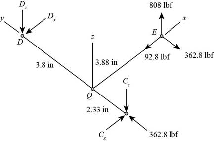
The free body diagram of the arrangement of shafts is shown in the figure below.

Figure (1)
Write the expression of moment at
Here, the reaction at
Write the expression of moment at
Here, the reaction at
Write the expression of moment at
Here, the reaction at
Write the expression of moment at
Write the expression of net force at
Here, the reaction at
It is clear from the free body diagram of the shaft
The calculations for shear force diagram in
Write the expression of Shear force at
Here, the shear at
Write the expression of Shear force at
Here, the shear force at
Write the expression of Shear force at
Here, the shear force at
The calculations for bending moment diagram in
We known that, the bending moment at the supports of the simply supported beam is zero.
Write the bending moment at
Here, the bending moment at
Write the expression of bending moment at
Here, the bending moment at
Write the expression of bending moment at
Here, the bending moment at
The calculations for shear force diagram in
Write the expression of Shear force at
Here, the shear at
Write the expression of Shear force at
Here, the shear force at
Write the expression of Shear force at
Here, the shear force at
We known that, the bending moment at the supports of the simply supported beam is zero.
Write the bending moment at
Here, the bending moment at
Write the expression of bending moment at
Here, the bending moment at
It is clear from the bending moment diagram that the critical stress element is located at just right of
Write the expression of maximum torque acting on the shaft
Here, the maximum torque acting on the shaft
Write the expression of maximum bending moment acting on the shaft
Here, the maximum bending moment acting on the shaft
Write the expression of torsional shear stress for critical stress element.
Here, the torsional shear stress for critical stress element is
Write the expression of bending stress for critical stress element.
Here, the bending stress for critical stress element is
Write the expression of axial stress for critical stress element.
Here, the axial stress for critical stress element is
Write the expression for von Mises alternating stress.
Here, the amplitude component of the axial stress is
Write the expression for von Mises mid-range stress.
Here, the mid-range component of the axial stress is
Write the expression for von Mises maximum stress.
Here, the maximum component of the axial stress is
Write the expression for yield factor of safety.
Here, the yield strength of the material is
Write the expression for endurance limit for test specimen.
Here, the minimum tensile strength is
Write the surface factor for the countershaft.
Here, the constants for surface factor are
Write the size factor for the countershaft.
Write the endurance limit at the critical location of the machine part.
Write the modified Goodman equation.
Here, the fatigue factor of safety is
Conclusion:
Substitute
Substitute
Substitute
Substitute
Substitute
Substitute
Substitute
Substitute
Substitute
Substitute
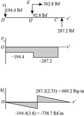
The figure below shows the shear force and bending moment diagram in

Figure-(2)
Substitute
Substitute
Substitute
Substitute
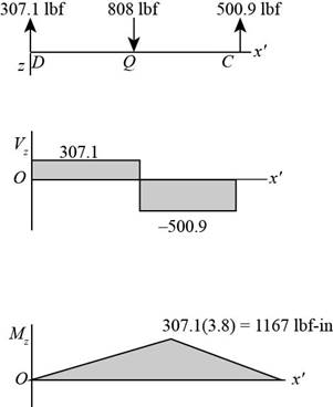
The figure below shows the shear force and bending moment diagram in

Figure (3)
Substitute
Substitute
Substitute
Substitute
Substitute
Substitute
Substitute
Write the expression for the maximum stress.
Substitute
Substitute
Refer to the Table A-20 “Deterministic ASTM Minimum Tensile and Yield Strengths for Some Hot-Rolled (HR) and Cold-Drawn (CD) Steels” to obtain the yield strength as
Substitute
Substitute
Refer to Table 6-2 “Parameters for Marin Surface Modification Factor” to obtain
Substitute
Substitute
Substitute
Substitute
Thus, the minimum factor of safety for fatigue based on infinite life is
Want to see more full solutions like this?
Chapter 6 Solutions
Shigley's Mechanical Engineering Design (McGraw-Hill Series in Mechanical Engineering)
- For the beam show below, draw A.F.D, S.F.D, B.M.D 6 kN/m 1 M B. 3 M Marrow_forward1. Two long rods of the same diameter-one made of brass (k=85w/m.k) and the other made of copper (k=375 w/m.k) have one of their ends inserted into a furnace (as shown in the following figure). Both rods are exposed to the same environment. At a distance of 105 mm from the furnace, the temperature of the brass rod is 120°C. At what distance from the furnace will the same temperature be reached in the copper rod? Furnace 105 mm T₁ Brass rod ⑪ h Too- x2- Ti Copper rodarrow_forward: +0 العنوان use only Two rods fins) having same dimensions, one made orass (k = 85 Wm K) and the mer of copper (k = 375 W/m K), having of their ends inserted into a furna. At a section 10.5 cm a way from furnace, the temperature of brass rod 120 Find the distance at which the ame temperature would be reached in the per rod ? both ends are ex osed to the same environment. ns 2.05 ۲/۱ ostrararrow_forward
- مشر on ۲/۱ Two rods (fins) having same dimensions, one made of brass(k=85 m K) and the other of copper (k = 375 W/m K), having one of their ends inserted into a furnace. At a section 10.5 cm a way from the furnace, the temperature brass rod 120°C. Find the distance at which the same temperature would be reached in the copper rod ? both ends are exposed to the same environment. 22.05 ofthearrow_forwardThe composite wall of oven with A= 1m² as in Fig.1 consists of three materials, two of with kA = 20 W/m K and kc = 50 W/m K with thickness, LA=0.3 m, L= 0.15 m and Lc 0.15 m. The inner surface temperature T1=900 K and the outer surface temperature T4 300 K, and an oven air temperature of To=1100 K, h=25 W/m². K. Determine kɛ and the temperatures T2 and T3 also draw the thermal resistance networkarrow_forwardTwo rods (fins) having same dimensions, one made of brass (k = 85 Wm K) and the other of copper (k = 375 W/m K), having one of their ends inserted into a furnace. At a section 10.5 cm a way from the furnace, the temperature of brass rod 120°C. Find the distance at which the same temperature would be reached in the copper rod ? both ends are exposed to the same environment. Ans 22.05arrow_forward
- A long wire (k-8 W/m °C.) with ro 5 mm and surface temperature Ts=180°C as shown in Fig.2. Heat is generated in the wire uniformly at a rate of 5 x10⁷ W/m³. If the energy equation is given by: d 11(77) + - =0 k r dr dr Derive an expression for T(r) and determine the temperature at the center of the wire and at r=2 mm. Air Th T KA LA T2 T3 T Fig.1 KB kc 180°C Го Fig.2arrow_forwardB: Find the numerical solution for the 2D equation below and calculate the temperature values for each grid point shown in Fig. 2 (show all steps). (Do only one trail using following initial values and show the final matrix) T₂ 0 T3 0 I need a real solution, not artificial intelligence locarrow_forwardCan I solve this problem by calculating the initial kinetic energy with respect to G instead of A.arrow_forward
- B: Find the numerical solution for the 2D equation below and calculate the temperature values for each grid point shown in Fig. 2 (show all steps). (Do only one trail using following initial values and show the final matrix) T₂ 0 T3 0 locarrow_forwardShow all work. Indicate the origin that is used for each plane. Identify the Miller indices for the following planes. N 23 1 A) X B) yarrow_forwardthe following table gives weight gain time data for the oxidation of some metal at an elevated temperature W(mg/cm2). Time (min) 4.66 20 11.7 50 41.1 175 a) determin whether the oxidation kinetics obey a linear, parabolic, or logarithmic rate expression. b) Now compute W after a time of 1000 minarrow_forward
 Mechanics of Materials (MindTap Course List)Mechanical EngineeringISBN:9781337093347Author:Barry J. Goodno, James M. GerePublisher:Cengage Learning
