
Vector Mechanics for Engineers: Statics and Dynamics
11th Edition
ISBN: 9780073398242
Author: Ferdinand P. Beer, E. Russell Johnston Jr., David Mazurek, Phillip J. Cornwell, Brian Self
Publisher: McGraw-Hill Education
expand_more
expand_more
format_list_bulleted
Concept explainers
Videos
Textbook Question
Chapter 5.3, Problem 5.72P
5.68 through 5.73 Determine the reactions at the beam supports for the given loading.
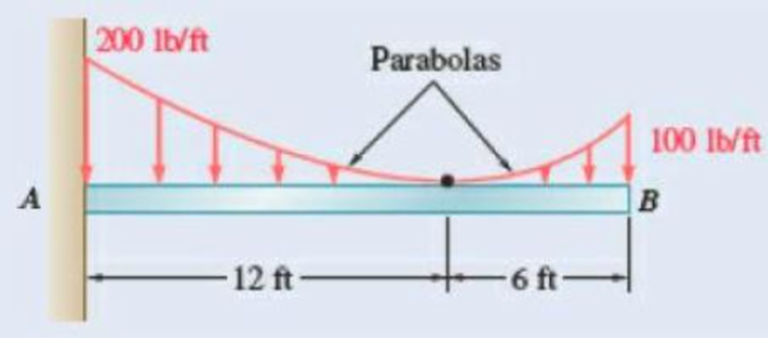
Fig. P5.72
Expert Solution & Answer
Want to see the full answer?
Check out a sample textbook solution
Students have asked these similar questions
5.76 Determine the reactions at the beam supports for the given loading when wo = 150 lb/ft.
Answer
450 lb/ft
44.1 kip-ft
12 ft
CA
2 ft
Wo
D
2. For the beam shown:
a. Draw the free-body diagram of
the beam.
1.8 m 1.8 m
b. Determine the reactions at the
supports.
0.80 kN
1.38 kN
25°
A
1,5 m.
2,1 m
5.60 A derrick carries a 12-Mg crate as shown. Determine the tensions in the
cables BF and BG and the reaction from the support at A.
4 m
4 m
6 m
Fig. P5.60
B
O
12 m
12 Mg
EA
12 m
4 m
3 m
k
Chapter 5 Solutions
Vector Mechanics for Engineers: Statics and Dynamics
Ch. 5.1 - 5.1 through 5.9 Locate the centroid of the plane...Ch. 5.1 - 5.1 through 5.9 Locate the centroid of the plane...Ch. 5.1 - 5.1 through 5.9 Locate the centroid of the plane...Ch. 5.1 - Locate the centroid of the plane area shown.Ch. 5.1 - 5.1 through 5.9 Locate the centroid of the plane...Ch. 5.1 - Locate the centroid of the plane area shown.Ch. 5.1 - Prob. 5.7PCh. 5.1 - Locate the centroid of the plane area shown.Ch. 5.1 - Locate the centroid of the plane area shown.Ch. 5.1 - Locate the centroid of the plane area shown.
Ch. 5.1 - Prob. 5.11PCh. 5.1 - Locate the centroid of the plane area shown.Ch. 5.1 - Prob. 5.13PCh. 5.1 - 5.10 through 5.15 Locate the centroid of the plane...Ch. 5.1 - Prob. 5.15PCh. 5.1 - PROBLEM 5.16 Determine the y coordinate of the...Ch. 5.1 - Show that as r1 approaches r2, the location of the...Ch. 5.1 - Prob. 5.18PCh. 5.1 - Prob. 5.19PCh. 5.1 - Prob. 5.20PCh. 5.1 - Prob. 5.21PCh. 5.1 - The horizontal x-axis is drawn through the...Ch. 5.1 - PROBLEM 5.23 The first moment of the shaded area...Ch. 5.1 - Prob. 5.24PCh. 5.1 - Prob. 5.25PCh. 5.1 - Prob. 5.26PCh. 5.1 - A thin, homogeneous wire is bent to form the...Ch. 5.1 - Prob. 5.28PCh. 5.1 - The frame for a sign is fabricated from thin, flat...Ch. 5.1 - The homogeneous wire ABCD is bent as shown and is...Ch. 5.1 - The homogeneous wire ABCD is bent as shown and is...Ch. 5.1 - Prob. 5.32PCh. 5.1 - Knowing that the distance h has been selected to...Ch. 5.2 - 5.34 through 5.36 Determine by direct integration...Ch. 5.2 - 5.34 through 5.36 Determine by direct integration...Ch. 5.2 - 5.34 through 5.36 Determine by direct integration...Ch. 5.2 - 5.37 through 5.39 Determine by direct integration...Ch. 5.2 - 5.37 through 5.39 Determine by direct integration...Ch. 5.2 - Prob. 5.39PCh. 5.2 - 5.40 and 5.41 Determine by direct integration the...Ch. 5.2 - 5.40 and 5.41 Determine by direct integration the...Ch. 5.2 - 5.42 Determine by direct integration the centroid...Ch. 5.2 - 5.43 and 5.44 Determine by direct integration the...Ch. 5.2 - 5.43 and 5.44 Determine by direct integration the...Ch. 5.2 - 5.45 and 5.46 A homogeneous wire is bent into the...Ch. 5.2 - 5.45 and 5.46 A homogeneous wire is bent into the...Ch. 5.2 - A homogeneous wire is bent into the shape shown....Ch. 5.2 - 5.48 and 5.49 Determine by direct integration the...Ch. 5.2 - Prob. 5.49PCh. 5.2 - Prob. 5.50PCh. 5.2 - Determine the centroid of the area shown when a =...Ch. 5.2 - Prob. 5.52PCh. 5.2 - 5.53 Determine the volume and the surface area of...Ch. 5.2 - Determine the volume and the surface area of the...Ch. 5.2 - Prob. 5.55PCh. 5.2 - Prob. 5.56PCh. 5.2 - Prob. 5.57PCh. 5.2 - Prob. 5.58PCh. 5.2 - Prob. 5.59PCh. 5.2 - Determine the capacity, in liters, of the punch...Ch. 5.2 - Determine the volume and total surface area of the...Ch. 5.2 - Prob. 5.62PCh. 5.2 - Determine the total surface area of the solid...Ch. 5.2 - Prob. 5.64PCh. 5.2 - The shade for a wall-mounted light is formed from...Ch. 5.3 - 5.66 and 5.67 For the beam and loading shown,...Ch. 5.3 - Prob. 5.67PCh. 5.3 - Prob. 5.68PCh. 5.3 - Prob. 5.69PCh. 5.3 - Prob. 5.70PCh. 5.3 - Prob. 5.71PCh. 5.3 - 5.68 through 5.73 Determine the reactions at the...Ch. 5.3 - 5.68 through 5.73 Determine the reactions at the...Ch. 5.3 - Determine (a) the distance a so that the vertical...Ch. 5.3 - Prob. 5.75PCh. 5.3 - 5.76 Determine the reactions at the beam supports...Ch. 5.3 - Prob. 5.77PCh. 5.3 - The beam AB supports two concentrated loads and...Ch. 5.3 - For the beam and loading of Prob. 5.78, determine...Ch. 5.3 - The cross section of a concrete dam is as shown....Ch. 5.3 - Prob. 5.81PCh. 5.3 - The dam for a lake is designed to withstand the...Ch. 5.3 - Prob. 5.83PCh. 5.3 - 5.84 An automatic valve consists of a 9 × 9-in....Ch. 5.3 - 5.85 An automatic valve consists of a 9 × 9-in....Ch. 5.3 - Prob. 5.86PCh. 5.3 - The 3 4-m side of an open tank is hinged at its...Ch. 5.3 - Prob. 5.88PCh. 5.3 - A 0.5 0.8-m gate AB is located at the bottom of a...Ch. 5.3 - Prob. 5.90PCh. 5.3 - Prob. 5.91PCh. 5.3 - Prob. 5.92PCh. 5.3 - Prob. 5.93PCh. 5.3 - Prob. 5.94PCh. 5.3 - The square gate AB is held in the position shown...Ch. 5.4 - Consider the composite body shown. Determine (a)...Ch. 5.4 - Prob. 5.97PCh. 5.4 - Prob. 5.98PCh. 5.4 - Prob. 5.99PCh. 5.4 - Prob. 5.100PCh. 5.4 - Prob. 5.101PCh. 5.4 - Prob. 5.102PCh. 5.4 - Prob. 5.103PCh. 5.4 - For the machine element shown, locate the y...Ch. 5.4 - For the machine element shown, locate the x...Ch. 5.4 - 5.106 and 5.107 Locate the center of gravity of...Ch. 5.4 - 5.106 and 5.107 Locate the center of gravity of...Ch. 5.4 - A corner reflector for tracking by radar has two...Ch. 5.4 - A wastebasket, designed to fit in the corner of a...Ch. 5.4 - Prob. 5.110PCh. 5.4 - Prob. 5.111PCh. 5.4 - Prob. 5.112PCh. 5.4 - Prob. 5.113PCh. 5.4 - A thin steel wire with a uniform cross section is...Ch. 5.4 - The frame of a greenhouse is constructed from...Ch. 5.4 - Locate the center of gravity of the figure shown,...Ch. 5.4 - PROBLEM 5.117 Locate the center of gravity of the...Ch. 5.4 - A scratch awl has a plastic handle and a steel...Ch. 5.4 - Prob. 5.119PCh. 5.4 - PROBLEM 5.120 A brass collar, of length 2.5 in.,...Ch. 5.4 - Prob. 5.121PCh. 5.4 - Prob. 5.122PCh. 5.4 - Prob. 5.123PCh. 5.4 - Prob. 5.124PCh. 5.4 - PROBLEM 5.125 Locate the centroid of the volume...Ch. 5.4 - PROBLEM 5.126 Locate the centroid of the volume...Ch. 5.4 - Prob. 5.127PCh. 5.4 - Prob. 5.128PCh. 5.4 - PROBLEM 5.129 Locate the centroid of the volume...Ch. 5.4 - Prob. 5.130PCh. 5.4 - Prob. 5.131PCh. 5.4 - PROBLEM 5.132 The sides and the base of a punch...Ch. 5.4 - Locate the centroid of the section shown, which...Ch. 5.4 - Prob. 5.134PCh. 5.4 - Prob. 5.135PCh. 5.4 - Alter grading a lot, a builder places four stakes...Ch. 5 - 5.137 and 5.138 Locate the centroid of the plane...Ch. 5 - 5.137 and 5.138 Locate the centroid of the plane...Ch. 5 - Prob. 5.139RPCh. 5 - Prob. 5.140RPCh. 5 - Prob. 5.141RPCh. 5 - Prob. 5.142RPCh. 5 - Determine the reactions at the supports for the...Ch. 5 - A beam is subjected to a linearly distributed...Ch. 5 - Prob. 5.145RPCh. 5 - Prob. 5.146RPCh. 5 - An 8-in.-diameter cylindrical duct and a 4 8-in....Ch. 5 - Three brass plates are brazed to a steel pipe to...
Knowledge Booster


Learn more about
Need a deep-dive on the concept behind this application? Look no further. Learn more about this topic, mechanical-engineering and related others by exploring similar questions and additional content below.Similar questions
- 5.82 The simply supported wood beam, fabricated by gluing together fourwooden boards, carries the three concentrated forces. The working bending and shear stresses for the wood are 1000 psi and 600 psi, respectively. Determine the largest allowable value of the force P.arrow_forwardProblem 5.3 The beam is subjected to a load F = 400 N and is supported by the rope and the smooth surfaces at A and B. 30° (a) Draw the free-body diagram of the beam. (b) What are the magnitudes of the reactions at A and B? -1.2 1m-arrow_forward3.1 A uniform horizontal beam has a length of 8 m and mass of 500 kg. The beam rests on two supports overhanging one by a distance x while the other is at the extreme right-hand end. The loading is 5 tonnes at the left-hand end, 6 tonnes at the mid-point of the beam and 7 tonnes 1 metre from the right-hand end. Determine the value of x if the reaction at the left-hand support is to be twice that at the right-hand support.- Show free-body-diagram and all your workings.arrow_forward
- ► 5.76 State whether each of the L-shaped bars shown is properly or improperly supported. If a bar is properly supported, determine the reactions at its supports. (See Active Example 5.6.) A F H B |²| (1) A INTIN F (3) MA F -L- (2)arrow_forward5.41 The inverted T-beam supports three concentrated loads as shown in the fig- ure. Find the maximum allowable value of Pif the bending stresses are not to exceed 3.5 ksi in tension and 8 ksi in compression. 14P 1.0 in. D 8 in. 1.0 in. 2 ft 3 ft 3 (t 2 tt - 4 int FIG. PS.41arrow_forwardThe connections at the ends of bars AB and BC are ball-and-socket joints. Neglecting the weights of the bars, determine the force in cable DE and the reaction at A. A 0.8 m E 4 -1 m- 800 N Fig. P5.60 m-arrow_forward
- Two reservours with different liquilds A (s.g 0.8) and B (s.g 1.5) are connected by a 1m square opening hole. The homogeneous cylinder (s.g 2.0), with 1 m long, is used to block the hole. Determine the magnitude and direction of the reactions at the upper and lower edges (s and m) of the opening. B S=0.8 6m A S=1.5 5m VZ m m 450 1marrow_forward96 Fundamentals of Biomechanics Determine the tensions T1 and T2 in the cables, weights W, and W2, and angle a that cable 1 makes with the horizontal, so that the leg remains in equilibrium at the position shown. Answers: T1 W1 = 223.6N T2= W2 = 282.8N a= 26.6° Problem 4.10 Consider the uniform, horizontal cantilever beam shown in Fig. 4.56. The beam is fixed at point A and a force that makes an angle B= 63° with the horizontal is applied at point B. The magnitude of the applied force is P=80 N. Point C is the center of gravity of the beam and the beam weighs W = 40 N and has a length 1 = 2 m. L. Fig. 4.56 Problem 4.10 Determine the reactions generated at the fixed end of the beam. Answers: RAr=36.3N (+x) RAy=111.3N(+y) MA=182.6 Mm (ccw) %3D %3D Problem 4.11 Consider the L-shaped beam illustrated in Fig. 4.57. The beam is welded to the wall at point A, the arm AB extends in the positive z direction, and the arm BC extends in the negative y direction. A force P is applied in the…arrow_forwardA beam in Fig. 3a and Fig. 3b is supported by a roller at A and a pin at C. Determine the horizontal and vertical components of support reactions on the beam if a = 3 m and L = 9 m for conditions in Fig. 3a and Fig. 3b, respectively.arrow_forward
- Two reservours with different liquilds A (s.g 0.8) and B (s.g 1.5) are connected by a 1m square opening hole. The homogeneous cylinder (s.g 2.0), with 1 m long, is used to block the hole. Determine the magnitude and direction of the reactions at the upper and lower edges (s and m) of the opening. S=0.8 6m A S=1.5 5m 45° Im inarrow_forwardThree loads are applied to a beam as shown. The beam is supported by a roller at A and by a pin at B. Neglecting the weight of the beam, determine the reactions at A and B when P = 15 kips 6 kips 6 kips B 6 ft 3 ft 2 ft ' 2 ftarrow_forward5 panels e L= SL W 45 Fig. P4.168 4.168 A couple acting on the winch at G slowly raises the load W by means of a rope that runs around the pulleys attached to the derrick at A and B. Determine the forces in members EF and KL of the derrick, assuming the diameters of the pulleys and the winch are negligible. %3B O 8 O O O Oarrow_forward
arrow_back_ios
SEE MORE QUESTIONS
arrow_forward_ios
Recommended textbooks for you
 Elements Of ElectromagneticsMechanical EngineeringISBN:9780190698614Author:Sadiku, Matthew N. O.Publisher:Oxford University Press
 Mechanics of Materials (10th Edition)Mechanical EngineeringISBN:9780134319650Author:Russell C. HibbelerPublisher:PEARSON
 Thermodynamics: An Engineering ApproachMechanical EngineeringISBN:9781259822674Author:Yunus A. Cengel Dr., Michael A. BolesPublisher:McGraw-Hill Education
 Control Systems EngineeringMechanical EngineeringISBN:9781118170519Author:Norman S. NisePublisher:WILEY
 Mechanics of Materials (MindTap Course List)Mechanical EngineeringISBN:9781337093347Author:Barry J. Goodno, James M. GerePublisher:Cengage Learning
 Engineering Mechanics: StaticsMechanical EngineeringISBN:9781118807330Author:James L. Meriam, L. G. Kraige, J. N. BoltonPublisher:WILEY
Elements Of Electromagnetics
Mechanical Engineering
ISBN:9780190698614
Author:Sadiku, Matthew N. O.
Publisher:Oxford University Press
Mechanics of Materials (10th Edition)
Mechanical Engineering
ISBN:9780134319650
Author:Russell C. Hibbeler
Publisher:PEARSON
Thermodynamics: An Engineering Approach
Mechanical Engineering
ISBN:9781259822674
Author:Yunus A. Cengel Dr., Michael A. Boles
Publisher:McGraw-Hill Education
Control Systems Engineering
Mechanical Engineering
ISBN:9781118170519
Author:Norman S. Nise
Publisher:WILEY
Mechanics of Materials (MindTap Course List)
Mechanical Engineering
ISBN:9781337093347
Author:Barry J. Goodno, James M. Gere
Publisher:Cengage Learning
Engineering Mechanics: Statics
Mechanical Engineering
ISBN:9781118807330
Author:James L. Meriam, L. G. Kraige, J. N. Bolton
Publisher:WILEY
Everything About COMBINED LOADING in 10 Minutes! Mechanics of Materials; Author: Less Boring Lectures;https://www.youtube.com/watch?v=N-PlI900hSg;License: Standard youtube license