
EBK PRINCIPLES OF ELECTRIC CIRCUITS
10th Edition
ISBN: 9780134880068
Author: Buchla
Publisher: VST
expand_more
expand_more
format_list_bulleted
Concept explainers
Videos
Textbook Question
Chapter 5, Problem 5P
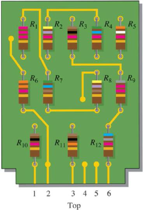
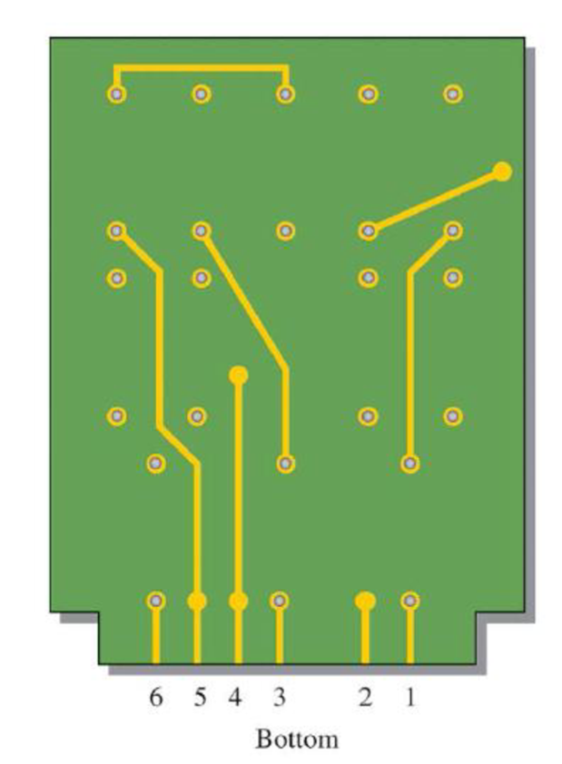
On the double-sided PC board in Figure 5–65, identify each group of series resistors. Note that many of the interconnections feed through the board from the top side to the bottom side.
Figure 5-65
Expert Solution & Answer
Want to see the full answer?
Check out a sample textbook solution
Students have asked these similar questions
Two identical resistor is connected in parallel then connected to series to another pair
identical of resistor, calculate the total resistance if the values are 10 ohms and 20
ohms respectively.
O 25 ohms
35 ohms
O 55 ohms
45 ohms
Determine the value of Rx in the balanced bridge in Figure 6-80.
All resistors are in parallel.
Chapter 5 Solutions
EBK PRINCIPLES OF ELECTRIC CIRCUITS
Ch. 5 - (a) Show how you would rewire the protoboard in...Ch. 5 - How is the circuit changed when pin 2 and pin 3 in...Ch. 5 - Determine the total resistance in Figure 5-10(a)...Ch. 5 - What is the total resistance for the following...Ch. 5 - Determine the value of R4 in Figure 5-12 if the...Ch. 5 - Find RT for three 1.0 k resistors and two 720 ...Ch. 5 - What is the value of R2 if the highest current is...Ch. 5 - Determine V3 if the polarity of VS2 is reversed in...Ch. 5 - Starting with Equation 5-5, prove that the...Ch. 5 - What is the power in the circuit of Figure 5-48 if...
Ch. 5 - Determine the minimum power rating required for...Ch. 5 - Assume that R1 is shorted In Figure 5-61. What...Ch. 5 - A series circuit can have more than one path for...Ch. 5 - The total resistance of a series circuit can be...Ch. 5 - If two series resistors are different sizes, the...Ch. 5 - If two series resistors are different sizes, the...Ch. 5 - If three equal resistors are used in a voltage...Ch. 5 - There is no valid electrical reason for installing...Ch. 5 - Kirchhoffs voltage law is valid only if a loop...Ch. 5 - Prob. 8TFQCh. 5 - Prob. 9TFQCh. 5 - If point A in a circuit has a voltage of +10 V and...Ch. 5 - Two equal-value resistors are connected in series...Ch. 5 - Prob. 2STCh. 5 - Prob. 3STCh. 5 - When one of four series resistors is removed from...Ch. 5 - Prob. 5STCh. 5 - A 9 V battery is connected across a series...Ch. 5 - While putting four 1.5 V batteries in a four-cell...Ch. 5 - If you measure all the voltage drops and the...Ch. 5 - There are six resistors in a given series circuit...Ch. 5 - A series circuit consists of a 4.7 k, a 5.6 k, and...Ch. 5 - Which of the following series combinations...Ch. 5 - The total power in a certain circuit is 1 W. Each...Ch. 5 - When you connect an ammeter in a series-resistive...Ch. 5 - While checking out a series-resistive circuit, you...Ch. 5 - With a 10 V voltage source connected between...Ch. 5 - For the conditions described in Question 1, the...Ch. 5 - When the switches are in position 1 and a short...Ch. 5 - When the switches are in position 2 and a short...Ch. 5 - If the current shown by one of the milliammeters...Ch. 5 - If the source voltage decreases, the current...Ch. 5 - If the current through R1 increases as a result of...Ch. 5 - If the switch is thrown from position A to...Ch. 5 - If the switch is thrown from position B to...Ch. 5 - If the switch is thrown from position C to...Ch. 5 - If R1 is changed to 1.2 k, the voltage from A to B...Ch. 5 - If R2 and R3 are interchanged, the voltage from A...Ch. 5 - If the source voltage increases from 8 V to 10 V,...Ch. 5 - Connect each set of resistors in Figure 563 in...Ch. 5 - Determine the groupings of resistors in Figure 564...Ch. 5 - Determine the nominal resistance between pins 1...Ch. 5 - Determine the nominal resistance between pins 2...Ch. 5 - On the double-sided PC board in Figure 565,...Ch. 5 - Prob. 6PCh. 5 - Prob. 7PCh. 5 - Calculate RT for each circuit of Figure 566....Ch. 5 - What is the total resistance of twelve 5.6 k...Ch. 5 - Six 56 resistors, eight 100 resistors, and two...Ch. 5 - Prob. 11PCh. 5 - You have the following resistor values available...Ch. 5 - Find the total resistance in Figure 566 if all...Ch. 5 - What is the total resistance from A to B for each...Ch. 5 - What is the current through each resistor in a...Ch. 5 - The current from the source in Figure 569 is 5 mA....Ch. 5 - Show how to connect a voltage source and an...Ch. 5 - Using 1.5 V batteries, a switch, and three lamps,...Ch. 5 - What is the current in each circuit of Figure 570?...Ch. 5 - Determine the voltage drop across each resistor in...Ch. 5 - Three 470 resistors are connected in series with...Ch. 5 - Four equal-value resistors are in series with a 5...Ch. 5 - What is the value of each resistor in Figure 571?...Ch. 5 - Determine VR1, R2, and R3 in Figure 5-72. Figure...Ch. 5 - For the circuit in Figure 573 the meter reads 7.84...Ch. 5 - Determine the current measured by the meter in...Ch. 5 - Refer to Figure 5-75. Assume the green LED drops...Ch. 5 - Refer to Figure 5-76. Assume there is a 2.0 V drop...Ch. 5 - Series aiding is a term sometimes used to describe...Ch. 5 - The term series opposing means that sources are in...Ch. 5 - Determine the total source voltage in each circuit...Ch. 5 - Prob. 32PCh. 5 - Five resistors are in series with a 20 V source....Ch. 5 - Determine the unspecified voltage drop(s) in each...Ch. 5 - In the circuit of Figure 5-79, determine the...Ch. 5 - Find R1, R2, and R3 in Figure 580. Figure 580Ch. 5 - Determine the voltage across R5 for each position...Ch. 5 - The total resistance of a circuit is 560 . What...Ch. 5 - Determine the voltage between points A and B in...Ch. 5 - Determine the voltage with respect to ground for...Ch. 5 - Determine the minimum and maximum voltage from the...Ch. 5 - What is the voltage across each resistor in Figure...Ch. 5 - Prob. 44PCh. 5 - If there are 10 V across R1 in Figure 5-86, what...Ch. 5 - Prob. 46PCh. 5 - Prob. 47PCh. 5 - Five series resistors each handle 50 mW. What is...Ch. 5 - If you double the voltage across a resistor, by...Ch. 5 - If the total resistance of a circuit is halved,...Ch. 5 - What is the total power in the circuit in Figure...Ch. 5 - The following W resistors are in series: 1.2 k,...Ch. 5 - Find RT in Figure 587.Ch. 5 - A certain series circuit consists of a W...Ch. 5 - Determine the voltage at each point with respect...Ch. 5 - In Figure 589, how would you determine the voltage...Ch. 5 - Determine the voltage at each point with respect...Ch. 5 - In Figure 589, what is VAC?Ch. 5 - In Figure 589, what is VCA?Ch. 5 - A string of five series resistors is connected...Ch. 5 - By observing the meters in Figure 590, determine...Ch. 5 - What current would you measure in Figure 590(b) if...Ch. 5 - Table 52 shows the results of resistance...Ch. 5 - You measure 15 k between pins 5 and 6 on the PC...Ch. 5 - In checking out the PC board in Figure 591, you...Ch. 5 - The three groups of series resistors on the PC...
Knowledge Booster


Learn more about
Need a deep-dive on the concept behind this application? Look no further. Learn more about this topic, electrical-engineering and related others by exploring similar questions and additional content below.Similar questions
- 53. Find RT in Figure 5-87. ➤FIGURE 5-87 R₂ 12 V www = 5,6 ΜΩ R₁ = 4.8 V Ry www P = 21.5 μWarrow_forwardSECTION 5-6 Kirchhoff's Voltage Law 32. The following voltage drops are measured across three resistors in series: 5.5 V, 8.2 V, and 12.3 V. What is the value of the source voltage to which these resistors are connected? 33. Five resistors are in series with a 20 V source. The voltage drops across four of the resistors are 1.5 V, 5.5 V, 3 V, and 6 V. How much voltage is dropped across the fifth resistor? 34. Determine the unspecified voltage drop(s) in each circuit of Figure 5-78. Show how to connect a voltmeter to measure cach unknown voltage drop. ► FIGURE 5-78 2 V V2 3.2 V 8 V R 15 VE 2R 0.5 V 1.5 V 4 R 3R (b)arrow_forwardDetermine the unknown voltage drop, 5, in Figure 5-35. 12 V FIGURE 5-35 50 6V 15arrow_forward
- Determine the total parallel resistancearrow_forwardMost schematic diagrams are made up of _____. a. series circuits b. parallel circuits c. series-parallel circuits d. none of the abovearrow_forwardAn R-L series circuit contains two resistors and two inductors. The resistors are 86 k and 68 k . The inductors have inductive reactances of 24 k and 56 k . The total voltage is 480 volts. Find the voltage drop across the 56-k inductor.arrow_forward
- Determine the output voltage of the unbalanced bridge in Figure 6-81 for a temperature of 65°C. The thermistor has a nominal resistance of 1 k2 at 25°C and a positive temperature coef- ficient. Assume that its resistance changes 5 for each C° change in temperature. R₁ Thermistor R3 1.0 ΚΩ +9 V B3 VOO R₂ 1.0 ΚΩ R4 1.0 ΚΩ FIGURE 6-81arrow_forwardThree resistors 10 Q, 15 Q, and 20 Q are connected in series across a 48-V source. What is the voltage across the 15-Q resistor?arrow_forwarddraw a simple three reisistor series voltage divider that provides equal voltage division of a 180 volt source and draws 2 milamps of currentarrow_forward
- Some solar modules are connected together to form a solar array producing a total voltage of 9V and a current of 1.5A. If each solar module produces 4.5V and 0.5A then what must be the correct arrangement in that array? Connect 2 solar modules in series with 2 strings in parallel Connect 2 solar modules in series with 3 strings in parallel Connect 3 solar modules in series with 3 strings in parallel Connect 3 solar modules in series with 2 strings in parallelarrow_forward22. A 7-segment decoder/driver drives the display in Figure 6-78. If the waveforms are applied as indicated, determine the sequence of digits that appears on the display. BCD/7-seg Ao a b A1 Ag 2 Az Az 4 8. FIGURE 6-78arrow_forward28. For the multiplexer in Figure 6-79, determine the output for the following input states: D₁ = 0, D₁ = 1, D₂ = 1, D3 = 0, S₁ = 1, S₁ = 0. So S₁ Do D₁ D₂ D3 MUX } of G 0 1 2 3 Figure 6-79 Yarrow_forward
arrow_back_ios
SEE MORE QUESTIONS
arrow_forward_ios
Recommended textbooks for you
 Delmar's Standard Textbook Of ElectricityElectrical EngineeringISBN:9781337900348Author:Stephen L. HermanPublisher:Cengage Learning
 Electricity for Refrigeration, Heating, and Air C...Mechanical EngineeringISBN:9781337399128Author:Russell E. SmithPublisher:Cengage Learning
Delmar's Standard Textbook Of Electricity
Electrical Engineering
ISBN:9781337900348
Author:Stephen L. Herman
Publisher:Cengage Learning
Electricity for Refrigeration, Heating, and Air C...
Mechanical Engineering
ISBN:9781337399128
Author:Russell E. Smith
Publisher:Cengage Learning
Current Divider Rule; Author: Neso Academy;https://www.youtube.com/watch?v=hRU1mKWUehY;License: Standard YouTube License, CC-BY