
Electrical Engineering: Principles & Applications (7th Edition)
7th Edition
ISBN: 9780134484143
Author: Allan R. Hambley
Publisher: PEARSON
expand_more
expand_more
format_list_bulleted
Concept explainers
Videos
Textbook Question
Chapter 5, Problem 5.81P
Two loads. A and B, are connected in parallel across a 1-kV-rms 60-Hz line, as shown in Figure P5.81. Load A consumes 10 kW with a 90 percent lagging power facto. Load B has an apparent power of 15 ICVA with an 80 percent lagging power factor. Find the power, reactive power, and apparent power delivered by the source. What is the power factor seen by the source?
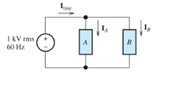
Figure P5.81
Expert Solution & Answer
Want to see the full answer?
Check out a sample textbook solution
Students have asked these similar questions
Don't use ai to answer i will report your answer
Don't use ai to answer I will report you answer
circuit value of i1 and i2
Chapter 5 Solutions
Electrical Engineering: Principles & Applications (7th Edition)
Ch. 5 - Consider the plot of the sinusoidal voltage...Ch. 5 - Repeat Problem P5.3 for v(t) = 50 sin (500t+120) .Ch. 5 - A sinusoidal voltage v(t) has an rms value of 20...Ch. 5 - A current i(t)=10cos(2000t) flows through a 100...Ch. 5 - We have a voltage v(t)=1000sin(500t) across a 500...Ch. 5 - Calculate the rms value of the half-wave rectified...Ch. 5 - We have v1(t)=10cos(t+30) . The current i1(t)has...Ch. 5 - Solve for the mesh currents shown in Figure P5.55.Ch. 5 - Two loads. A and B, are connected in parallel...
Knowledge Booster


Learn more about
Need a deep-dive on the concept behind this application? Look no further. Learn more about this topic, electrical-engineering and related others by exploring similar questions and additional content below.Similar questions
- In the circuit shown in the figure, the switch opens at time t = 0. For t≥ 0 use I(t) and V₁(t) or Find Vc(t) and lc(t). D to icht) w 43 ViLC+) + vc(+) 5. F + 1252 18 A 3) 2H2VLCH 8 V 4л warrow_forwardQ1/obtain the transfer function for the block diagram shown in the figure below: G4 Garrow_forwardQ4. Complete the missing readings (value and direction) in this table based on the circle shown below. With the presence of exporters With the presence of source 287 I₁ I2 13 4A. In the presence of the source 77 I.A 2A 28V= M ww 13 + tw 4A =7Varrow_forward
- Please solve in detailarrow_forward6.7 The transmitting aerial shown in Fig. Q.3 is supplied with current at 80 A peak and at frequency 666.66 kHz. Calculate (a) the effective height of the aerial, and (b) the electric field strength produced at ground level 40 km away. 60 m Fig. Q.3 Input 48 m Eartharrow_forwardox SIM 12.11 Consider the class B output stage, using MOSFETs, shown in Fig. P12.11. Let the devices have |V|= 0.5 V and μC WIL = 2 mA/V². With a 10-kHz sine-wave input of 5-V peak and a high value of load resistance, what peak output would you expect? What fraction of the sine-wave period does the crossover interval represent? For what value of load resistor is the peak output voltage reduced to half the input? Figure P12.11 +5 V Q1 Q2 -5Varrow_forward
arrow_back_ios
SEE MORE QUESTIONS
arrow_forward_ios
Recommended textbooks for you
 Power System Analysis and Design (MindTap Course ...Electrical EngineeringISBN:9781305632134Author:J. Duncan Glover, Thomas Overbye, Mulukutla S. SarmaPublisher:Cengage Learning
Power System Analysis and Design (MindTap Course ...
Electrical Engineering
ISBN:9781305632134
Author:J. Duncan Glover, Thomas Overbye, Mulukutla S. Sarma
Publisher:Cengage Learning
What is the Difference Between Single Phase and Three Phase???; Author: Electrician U;https://www.youtube.com/watch?v=FEydcr4wJw0;License: Standard Youtube License