
Concept explainers
Videos
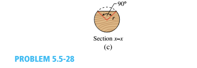
A foot bridge on a hiking trail is constructed using two timber logs each having a diameter d = 0.5 m (see figure a). The bridge is simply supported and has a length L = 4 m. The top of each log is trimmed to form the walking surface (see Fig, b)LA simplified model of the bridge is shown in Fig. g. Each log must carry its own weight w = 1.2 kN/m and the weight (P = 850 N) of a person at mid-span, (see Fig. b).
- Determine the maximum tensile and compressive stresses in the beam (Fig, b) due to bending.
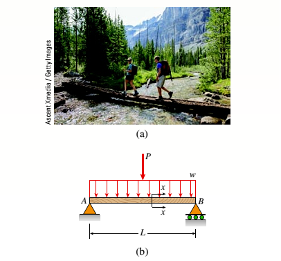
(a)
The maximum tensile stress in beam.
The maximum compressive stress in beam.
Answer to Problem 5.5.28P
The maximum tensile stresses in beam are
The maximum compressive stresses in beam are
Explanation of Solution
Given information:
The diameter of the timber log is
The length of the bridge is
The weight of the log is
The following figure shows the force distribution on the wooden log.
Figure 1
Write the expression for the area of the circle.
Here, the diameter of the circle is
Write the expressions for the polar moment of inertia of the circle.
Here, the polar moment of inertia is
Write the expression for centroidal distance.
Here, the centroidal distance of the circle is
Write the expressions for radius of circle.
Here, the radius of circle is
Write the expressions for the area of the circular segment.
Here, the radius of the circle is
Write the expression for the centroidal distance of the segment.
Here, the centroidal distance of the segment is
Write the expression for moment of inertia of the segment about x axis.
Here, the moment of inertia about x axis is
Write the expression for moment of inertia about z axis.
Here, the moment of inertia about z axis is
Write the expression for the distance from the centroid to the bottom.
Here, the distance of centroid from the bottom is
Write the expression for the distance from the centroid to the top.
...... (X)
Here, the distance from centroid to the top is
Write the expression for moment of inertia of the wooden beam.
Here, the net moment of inertia of the wooden beam is
Write the expression for maximum moment.
Here, the distributed load is
Write the expression for maximum tensile stress in mid span.
Here, the maximum tensile stress is
Write the expression for maximum compressive stress in mid span.
Here, the maximum compressive stress is
Calculation:
Substitute
Substitute
Substitute
Substitute
Substitute
Substitute
Substitute
Substitute
Substitute
Substitute
Substitute
Substitute
Substitute
Conclusion:
The maximum tensile stress in beam are
The maximum compressive stress in beam are
(b)
The maximum permissible value of load
Answer to Problem 5.5.28P
The maximum permissible value of load
Explanation of Solution
Given Information:
The allowable normal tensile stress is
The allowable normal compressible stress is
Write the expression for the maximum tensile moment.
Here the maximum tensile moment is
Write the expression for the maximum compressible moment.
Here the maximum compressive moment is
Write the expression for the tensile force corresponding to the permissible stress.
...... (XVII)
Calculation:
Substitute
Substitute
Substitute
Conclusion:
The maximum permissible value of load
Want to see more full solutions like this?
Chapter 5 Solutions
Bundle: Mechanics Of Materials, Loose-leaf Version, 9th + Mindtap Engineering, 1 Term (6 Months) Printed Access Card


- A large precast concrete panel for a warehouse is raised using two sets of cables at two lift lines, as shown in the figure part a. Cable 1 has a length L1 = 22 Ft, cable 2 has a length L2= 10 ft, and the distance along the panel between lift points Band D is d = 14 ft (see figure part b). The total weight of the panel is W = 85 kips. Assuming the cable lift Forces F at each lift line are about equal, use the simplified model of one half of the panel in figure part b to perform your analysis for the lift position shown. Find the required cross-sectional area AC of the cable if its breaking stress is 91 ksi and a factor of safety of 4 with respect to failure is desired.arrow_forwardA cylindrical brick chimney of height H weighs w = 825 lb/ft of height (see figure). The inner and outer diameters are d1= 3 ft and d2= 4 ft, respectively. The wind pressure against the side of the chimney is p = 10 lb/ft2 of projected area. Determine the maximum height H if there is to be no tension in the brickwork.arrow_forwardA flanged wooden shape is used to support the loads shown on the beam. The dimensions of the shape are shown in the second figure. Assume LAB = 7 ft, LBc = 3 ft, LCD= 3 ft, LDE = 2 ft, Pc= 2090 lb, PE = 1780 lb, WAB=710 lb/ft, b₁ = 10 in., b₂= 2 in., b3 = 7 in., d₂ = 2 in., d₂ = 7 in., d3=2 in. Consider the entire 15-ft length of the beam and determine: (a) the maximum tension bending stress o at any location along the beam, and (b) the maximum compression bending stress at any location along the beam. Answers: (a) OT: = (b) a = = WAB LAB 1018.59 829.57 B Pc LBC b₁ b3 C LCD psi. psi, D d₁ LDE d₂ d3 PE Earrow_forward
- A flanged wooden shape is used to support the loads shown on the beam. The dimensions of the shape are shown in the second figure. Assume LAB = 7 ft. LBC= 2 ft, LCD= 4 ft,LDE = 3 ft, Pc= 1720 lb, Pe=2360 lb, WAB=850 lb/ft, b₂ = 8 in., b₂ = 2 in., b3 = 4 in., d₁ = 2 in., d₂ = 12 in., d3= 2 in. Consider the entire 16-ft length of the beam and determine: (a) the maximum tension bending stress or at any location along the beam, and (b) the maximum compression bending stress ocat any location along the beam. Answers: (a) OT (b) oc= i = i WAB LAB B Pc LBC b₁ b3 C LCD ·b₂ OD psi. psi. d₁ d3 LDE PE Earrow_forwardA flanged wooden shape is used to support the loads shown on the beam. The dimensions of the shape are shown in the second figure. Assume LAB = 8 ft. LBc=2 ft, LCD= 4 ft, LDE= 4 ft, Pc = 1850 lb, PE = 2160 lb, WAB = 830 lb/ft, b₁ = 10 in., b2= 2 in., b3 = 6 in., d₁ = 2 in., d₂= 11 in., d3 = 2 in. Consider the entire 18-ft length of the beam and determine: (a) the maximum tension bending stress or at any location along the beam, and (b) the maximum compression bending stress oc at any location along the beam. Answers: (a) σT = (b) a = WAB LAB i 545.779 706.391 B Pc LBC b₁ b3 C LCD -b₂ psi. psi. D ↓ d₁ LDE d₂ PE Earrow_forwardA flanged wooden shape is used to support the loads shown on the beam. The dimensions of the shape are shown in the second figure. Assume LAB = 8 ft. LBc = 2 ft, LCD = 4 ft, LDE = 4 ft, PC= 1850 lb, PE = 2160 lb, WAB = 830 lb/ft, b₁ = 10 in., b₂ = 2 in., b3 = 6 in., d₁= 2 in., d₂ = 11 in., d3 = 2 in. Consider the entire 18-ft length of the beam and determine: (a) the maximum tension bending stress or at any location along the beam, and (b) the maximum compression bending stress oc at any location along the beam. Answers: (a) σT = (b) a = i WAB LAB 666.41 864.39 B Pc 1 LBC b₁ b3 C LCD -b₂ psi. psi. D d₁ d3 LDE PE E Xarrow_forward
- The Straw Hat crew on their journey to Laugh Tale Island found a big treasure box (W). Luffy wanted to place the treasure box (W) as shown in the figure. A 100-mm x 300 mm rectangular beam is supported in a horizontal position. At point "A", it is being held by a pin and at "B" by a cable BD inclined 3 vertical to 4 horizontal. Assume all forces are applied to the beam along its central axis. Given that Fcparallel to grain = 10.50 MPa, W = 79 kN and E = 13800 MPa. Neglecting the weight of the beam and cable, determine whether the design is safe. Cable 2.4 m 2.4 marrow_forwardA flanged wooden shape is used to support the loads shown on the beam. The dimensions of the shape are shown in the second figure. Assume LAB = 9 ft, LBC = 3 ft, LCD = 4 ft, LDE = 4 ft, PC = 2150 lb, PE = 2260 lb, wAB = 650 lb/ft, b1 = 11 in., b2 = 2 in., b3 = 7 in., d1 = 2 in., d2 = 5 in., d3 = 2 in. Consider the entire 20-ft length of the beam and determine:(a) the maximum tension bending stress σT at any location along the beam, and(b) the maximum compression bending stress σC at any location along the beam.arrow_forwardwe want to build a single-rail overhead crane in the workshop.when the load reaches the extreme point, it is 1800 mm away. the rail-shaped profile iron of the crane is connected from point B to point A by rope.the tensile stress of the rope is = 600 mpa. and the cross-sectional area is a=802 mm.according to other dimensions given (a=850mm b=1500 mm), this vince can hang No more than how many kg of load.(G=?)arrow_forward
- A new art exhibit featuring mobile works is going up in the Holland, MI, area. One piece is shown in the figure. The 155-N uniform beam is pinned to the ground by a pivot. The beam is supported by a cable (attached to the center of the beam) to allow for each of the shoes to hang freely. Each individual shoe has a weight of 9.5-N. If one shoe is attached two-fifths of the way up the beam and another shoe is attached and three-fifths of the way up the beam, with θc = 16.5° and θb = 33.6° as shown in the figure, what is the tension in the cable, in newtons? What is the x-component of the force, in newtons, that the pivot exerts on the bottom of the beam? Use the coordinate system specified in the figure. What is the y-component of the force, in newtons, that the hinge exerts on the bottom of the beam? Use the coordinate system specified in the figure.arrow_forwardA flanged wooden shape is used to support the loads shown on the beam. The dimensions of the shape are shown in the second figure. Assume LAB = 9 ft, LBc = 2 ft, LcD = 3 ft, LoE = 2 ft, Pc = 1920 Ib, PE = 2070 Ib, wAB = 810 Ib/ft, b1 = 8 in., b2= 2 in., b3= 6 in., dz = 2 in., d2= 11 in., d3= 2 in. Consider the entire 16-ft length of the beam and determine: (a) the maximum tension bending stress or at any location along the beam, and (b) the maximum compression bending stress oc at any location along the beam. PC PE WAB B |C D E LAB LBC LCD LDE b1 d |d2 - bz dz bz Answers: (a) or = i psi. (b) oc psi.arrow_forwardThe figure below shows two solid homogenous rectangular beam sections with (breadth x depth) dimensions in two different orientations as follows: Beam Section Orientation A (t mm x 2t mm); and Beam Section Orientation B (2t mm x tmm). Both beams sag when subjected to the same loading and support conditions resulting in compressive stresses above the centroid line (neutral axis). Which statement accurately describes the relative maximum compressive stress (ocompression) between these beam section orientations? O a. O b. Oc tmm 2 mm Beam Section Orientation A 2tmm 7 mm Beam Section Orientation B Maximum compressive stress (compression) in orientation B is greater than orientation A by a factor of 2. Maximum compressive stress (ocompression) in orientation A is greater than orientation B by a factor of 4. Maximum compressive stress (compression) in orientation B is greater than orientation A by a factor of 4. O d. Maximum compressive stress (ocompression) in orientation A is greater than…arrow_forward
 Mechanics of Materials (MindTap Course List)Mechanical EngineeringISBN:9781337093347Author:Barry J. Goodno, James M. GerePublisher:Cengage Learning