
(a)
Whether a
Answer to Problem 5.5.14P
Inadequate
Explanation of Solution
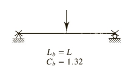
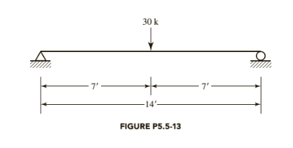
Given:

Formula used:
Lpis unbraced length in an inelastic behavior
Lris unbraced length in an elastic behavior
Mn is nominal moment strength
Mpis plastic moment capacity
Calculation:
All channel shapes in the Manual are compact.(There are no footnotes to indicate otherwise)
For an
A is Cross-sectional area
Sxis Elastic section modulus about X -axis
Zxis Plastic section modulus about X -axis
Iyis Moment of inertia about Y -axis
ryis Radius of gyration about Y -axis
Syis Elastic section modulus about Y -axis
Cwis Warping constant
h0is Distance between centroid of flanges
J is Torsional moment of inertia
For channels,
For
From the below given figure in the textbook,
Conclusion:
(b)
Whether a
Answer to Problem 5.5.14P
Inadequate
Explanation of Solution
Given:
Formula used:
Mn is nominal moment strength
Mpis plastic moment capacity
Calculation:
All channel shapes in the Manual are compact. (There are no footnotes to indicate otherwise)
For an
A is Cross-sectional area
Sxis Elastic section modulus about X -axis
Zxis Plastic section modulus about X -axis
Iyis Moment of inertia about Y -axis
ryis Radius of gyration about Y -axis
Syis Elastic section modulus about Y -axis
Cwis Warping constant
h0is Distance between centroid of flanges
J is Torsional moment of inertia
For channels,
For
From the below given figure in the textbook,

Conclusion:
Want to see more full solutions like this?
Chapter 5 Solutions
Bundle: Steel Design, Loose-leaf Version, 6th + Mindtap Engineering, 1 Term (6 Months) Printed Access Card

- A variable cross-sectional beam is pinned from the point B by BD bar as shown. Flexural rigidity of AB and BC beams are 2El and EI, respectively. If the axial rigidity of the BD bar is EA, Determine the reaction forces at the point A by using, Mohr method 7 AL ). 3 EA L P E2I C EIarrow_forwardA cantilevered structural member is fabricated with the cross section shown below and is eccentrically loaded with F. - 26 - 2t F Use G = 77.2 GPa. If I = 4 m, t = 3 mm, b = 80 mm, and F = 112 kN, Determine the maximum shear stress due to torsion. Select the correct response: 133.333 MPa 215.278 MPa 168.056 MPa 155.556 MPaarrow_forward250 mm A D P = 25 kN B 30 60 C TOP VIEW 280 mm Member AD is fabricated by joining two bars (E0=205GP,, Ga=82GPA) and is pinned to plate ABC using a 5 mm diameter pins as shown in the figure. The yield strength of the pins is T,=890MPA. Plate ABC is a right triangle and is fixed along its edge BC. A 25KN Force P is then applied at end D causing a lateral strain in member AD with magnitude equal to 7.5x10-mm/mm. This also causes Point A to displace only along the horizontal resulting to a shear strain at point A equal to y,=+0.00165rad. Determine the following: 1. Poisson's ratio of material used in member AD, vAD 2. The normal strain in member AD, caD 3. The average stress experienced by pin A, T, 4. Factor of Safety of pin A with respect to yielding, FS,A 5. Displacement of point D, A,arrow_forward
- A structural member is fabricated with the cross section show below and is eccentrically loaded with F. - 26--| F 2t F b. Use G = 77.2 GPa. If I = 4 m, t= 3 mm, b = 80 mm, and F = 121 kN, Determine the maximum shear stress due to torsion. Select the correct response: 168.056 MPa 215.278 MPa 155.556 MPa of 133.333 MPa 22arrow_forwardStrain in rods is zero prior to applying load Determine load P such that the axial stress in the steel pipe is 200 MPa P Imm GAP RIGIO PLATE .6m B RIGID SUPPORT 30 mm x 30 mm. AL BAR E = 73 GPA 100 mm E = 200 G PO A B A ØSTEEL PIPE w/ 5mm WALLarrow_forwardTwo reds vertically connect beam figure. Pcint A is fxed s shinged connected If the rod on the right is heated by 18 degree Celsius 2 m - 2 m 2 m Use E-200 GPa, linear of coeff cient expansion = 11.7x1o per degree celsius and A4509 mm Compute for the deformation of the right rodin mm Select the correct response 0.0234 mm 0.0842 mm 00468 mm 0.117 mmarrow_forward
- 2. Given a simply supported beam shown in figure below with the cross section at maximum moment. The beam supports a uniform service dead load of WDL =30 kN/m (excluding own weight of beam), PLL = 270 kN. Use fc' = 30 MPa; fy = 400 MPa. Calculate design strength M, for the cross section shown in the figure. Check the strains in the steel ɛsi. P, LL 75 100 - - 75 90 W. DL 710 650 5Ф30 15000 mm-arrow_forwardThe rigid bar AD (figure STR-4) is supported by two steel wires of 1.5mm diameter (E = 200 GPa) and a pin and bracket at D. Knowing that the wires were initially taut. Determine the following: a. The additional tension in wire BE when a load P=900 N is applied at D. b. The additional stress in wire FC when a load P = 900 N is applied at D c. The corresponding deflection at point D.arrow_forwardThe AD beam, which is fixed at left end, is under various loads as shown below. a) Draw internal load diagrams (Nx, Vy, M2) using the method of section. b) Determine the state of stress at points G, H and I for section B. c) For the corresponding points, indicate the results (i.e. stress components) on a differential element. b2 A B G М F2 2l h bi GIVEN DATA: Fo = 10000 N, F1 1200 N, F2 = 1000 N, qo = 50 N/cm, Mo = 50000 Nem, l = 25 cm bi = 10 cm, b2 = 20 cm, h 12 cm, t 1 cmarrow_forward
- A truss is loaded as shown in the figure. The cross- sectional area of each member is 500 mm^2. Hint: Use method of section in getting the axial forces. Use the guide cutting sections. L-6 m+6m- N 25 kN 8 m 50 kN - a 8 m 50 kN 8 m 50 kN 8 m B. 9. Find the axial stress in member HK O 35.34 MPa O 31.12 MPa O 33.34 MPa O 37.12 MPa Question 10 10. Find the axial stress in member HJ. O 125 MPa О 123 МPа O 127 MPa O 129 MPaarrow_forwardDetermine the design moment capacity of the beam with given properties below. bf = 550mm %3D bw = 350mm %3D tf = 50mm %D d = 370mm d' = 100mm %D fc' = 34.5 MPa %3D fy = 400 MPa As = 6 - 28mm bars %D a. USE NSCP 2001, Mu = kN-m b. USE NSCP 2015, Mu = kN-marrow_forwardConsider the simply supported truss as defined in the figure and parameter table. Find the force in members CD, HD, and HG. Follow the convention the tension is positive and compression is negative. A 1910 P. B cc 000 BY NỌ SA 2021 Cathy Zupke L₂ parameter value L₁ 1.5 L2 1.5 L3 2.5 LA 2 1.5 1.5 30 50 60 60 L5 L6 P₁ P₂ P3 P₁ units H # G P₁ E F The force in member CD = The force in member HD = The force in member HG = m m EEEEEZZ m m m L3 KN KN ↑ KN KN KN 3arrow_forward

 Structural Analysis (10th Edition)Civil EngineeringISBN:9780134610672Author:Russell C. HibbelerPublisher:PEARSON
 Principles of Foundation Engineering (MindTap Cou...Civil EngineeringISBN:9781337705028Author:Braja M. Das, Nagaratnam SivakuganPublisher:Cengage Learning
 Fundamentals of Structural AnalysisCivil EngineeringISBN:9780073398006Author:Kenneth M. Leet Emeritus, Chia-Ming Uang, Joel LanningPublisher:McGraw-Hill Education
 Traffic and Highway EngineeringCivil EngineeringISBN:9781305156241Author:Garber, Nicholas J.Publisher:Cengage Learning