
Concept explainers
Videos
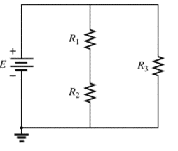
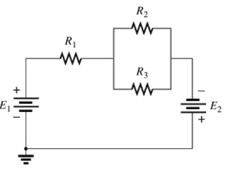
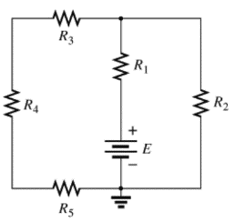
For each configuration in Fig. 5.88, find the individual (not combinations of) elements (voltage sources and/or resistors) that are in series.
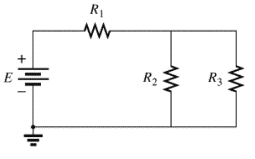
(a)
The individual elements that are connected in series for the given configuration.
Answer to Problem 1P
The individual elements that are connected in series for the given configuration are
Explanation of Solution
Given:
The circuit is given below.
Calculation:
The given circuit is analyzed by the rules of series-parallel combination.
As per the series combination rule,
Conclusion:
(b)
The individual elements that are connected in series for the given configuration.
Answer to Problem 1P
The individual elements that are connected in series for the given configuration are
Explanation of Solution
Given:
The circuit is given below,
Calculation:
The given circuit is analyzed by the rules of series-parallel combination.
As per the series combination rule,
Conclusion:
(c)
The individual elements that are connected in series for the given configuration.
Answer to Problem 1P
The individual elements that are connected in series for the given configuration are
Explanation of Solution
Given:
The circuit is given below,
Calculation:
The given circuit is analyzed by the rules of series-parallel combination.
As per the series combination rule,
Conclusion:
(d)
The individual elements that are connected in series for the given configuration.
Answer to Problem 1P
The individual elements that are connected in series for the given configuration are
Explanation of Solution
Given:
The circuit is given below,
Calculation:
The given circuit is analyzed by the rules of series-parallel combination.As per the series combination rule of resistances,
Conclusion:
Therefore,
Want to see more full solutions like this?
Chapter 5 Solutions
Laboratory Manual for Introductory Circuit Analysis
Additional Engineering Textbook Solutions
Fundamentals of Applied Electromagnetics (7th Edition)
Electrical Engineering: Principles & Applications (7th Edition)
Modern Database Management
Foundation Design: Principles and Practices (3rd Edition)
Web Development and Design Foundations with HTML5 (8th Edition)
C++ How to Program (10th Edition)


- Provde a 5 capstone project that can be done by electrical engineering student. Thank you.arrow_forwardDraw a schematic of a circuit that converts the thermistor resistance to a measurable voltage. I suggest basing it on the only circuit you have studied so far: the voltage divider. Assuming that you have a negative-thermal coecient (NTC) thermistor and that you want higher temperature to result in higher voltage, which of the resistors in a voltage divider is the thermistor and which is a fixed resistor? Use the proper thermistor symbol and put the thermistor part number on the schematic. (For the final report, update this schematic with the resistor value chosen in the lab.)arrow_forwardA 0 – 150 voltmeter has a resistance of 2000-ohms per volt. It is desired to change this voltmeter to a 0 – 600 volt instrument by the edition of an external multiplier. What is the resistance, in ohms, of this external multiplier?arrow_forward
- For the circuit shown in figure 5, make use of superposition as solution method. 5.1) Calculate the voltage in volts at node V0 when the 3 V source is deactivated. 5.2) Calculate the voltage in volts at node V0 when the 9 V source is deactivated. 5.3) Calculate the final voltage V0 in volts for the circuit.arrow_forwardConvert the following diagrams to circuit diagram.arrow_forwardBreadboard Projects Propose a SIMPLE PROJECT with the use of Basic Electronic Components and Define why you’ve chosen/decided to propose that project? What is itsimportance? Requirements :Title of the Project:Its Importance:List of Components:Breadboard Layout:arrow_forward
- In figure 5.1 of Experiment # 5, what is the computed value of RTH? Show the complete solution. 752 1502 A 5V 2202 4702 B RTH Blank 1 0 (type your answer with 2 decimal places)arrow_forwardHow would you improve this circuit? Draw a diagramarrow_forwardShow and COMPLETE solutions. Draw all CIRCUIT DIAGRAMS or the equivalent circuit (dummy circuit) as the case may be. A battery is to consist of 20 identical cells. The emf of each cell is 1.5 V and the internal resistance is 0.20 ohm. This battery will be used to supply power to a 10-ohm lamp. Determine thecurrent on the lamp if: The 20 cells are arranged 5 cells in series in 4 parallel rows.arrow_forward
- Draw a schematic (circuit) diagram of four resistors connected to a source (EMF) , where should have the same current with the total current in the circuit, while share this total amount of current at the same time. have the same values with the following color bands: red, black, red, gold; while also have the same values with the following color bands: yellow, violet, brown, gold. Applying the rules in series and parallel circuits as well as Ohm's law, discuss your complete solution conceptually and mathematically. In your own words, discuss comprehensively your strategic analysis on how to solve the problem. Show logical and systematic computations to solve for the unknowns. Present your evaluated data (final answers) in a tabular matrix. Express your final answers in two decimal places. Use the template below.arrow_forwardConvert the diagrams to circuit diagramsarrow_forwardEvaluate the circuits (a and b) below and determine the voltage of VS1 for both circuits.arrow_forward
 Introductory Circuit Analysis (13th Edition)Electrical EngineeringISBN:9780133923605Author:Robert L. BoylestadPublisher:PEARSON
 Delmar's Standard Textbook Of ElectricityElectrical EngineeringISBN:9781337900348Author:Stephen L. HermanPublisher:Cengage Learning
 Programmable Logic ControllersElectrical EngineeringISBN:9780073373843Author:Frank D. PetruzellaPublisher:McGraw-Hill Education
 Fundamentals of Electric CircuitsElectrical EngineeringISBN:9780078028229Author:Charles K Alexander, Matthew SadikuPublisher:McGraw-Hill Education
 Electric Circuits. (11th Edition)Electrical EngineeringISBN:9780134746968Author:James W. Nilsson, Susan RiedelPublisher:PEARSON
 Engineering ElectromagneticsElectrical EngineeringISBN:9780078028151Author:Hayt, William H. (william Hart), Jr, BUCK, John A.Publisher:Mcgraw-hill Education,