Concept explainers
(a)
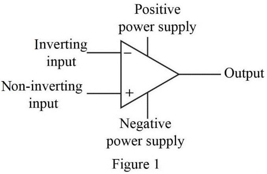
Label the five terminals in the operational amplifier.
(a)
Explanation of Solution
Given data:
Refer to Figure P5.1 in the textbook for the ideal op amp circuit.
Discussion:
The five terminals of the op amp are labeled as shown in Figure 1.

Conclusion:
Thus, the five op-amp terminals with their names are labeled as shown in Figure 1.
(b)
Mention the ideal op amp constraint that determines the value of
(b)
Answer to Problem 1P
The input resistance of the op amp constraints determines the value of
Explanation of Solution
Discussion:
The input resistance available at the input terminals will determines the current value
Conclusion:
Thus, the input resistance of the op amp constraints determines the value of
(c)
Mention the ideal op amp constraints that determines the value of
(c)
Answer to Problem 1P
The open loop voltage gain of the op amp constraints the value of
Explanation of Solution
Discussion:
The open loop voltage gain of an ideal op amp determines the value of
Conclusion:
Thus, the open loop voltage gain of the op amp constraints the value of
(d)
Find the value of voltage
(d)
Answer to Problem 1P
The value of voltage
Explanation of Solution
PSpice Simulation:
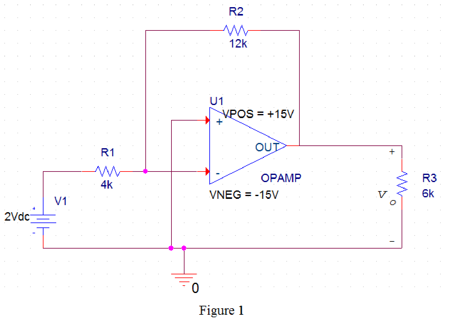
Draw the given circuit in PSPICE as shown in Figure 1.

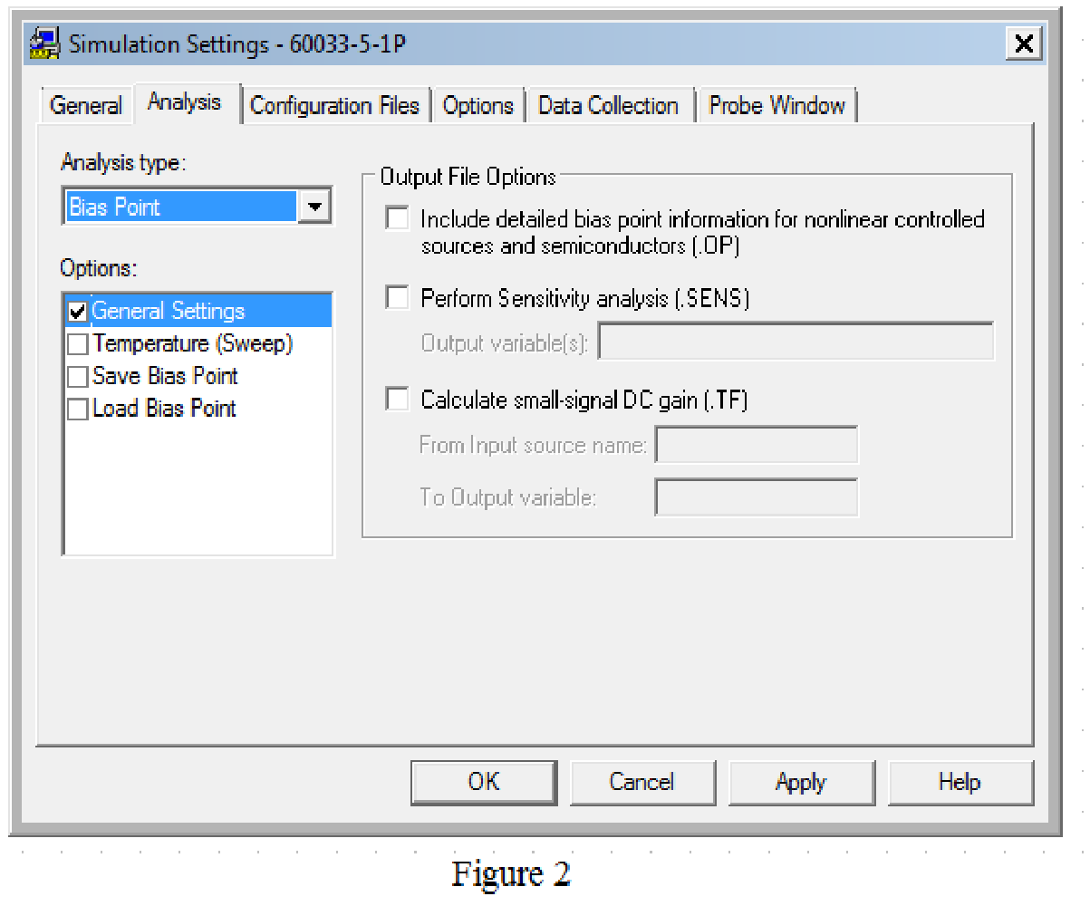
Provide the simulation settings as shown in Figure 2 to obtain output parameters.

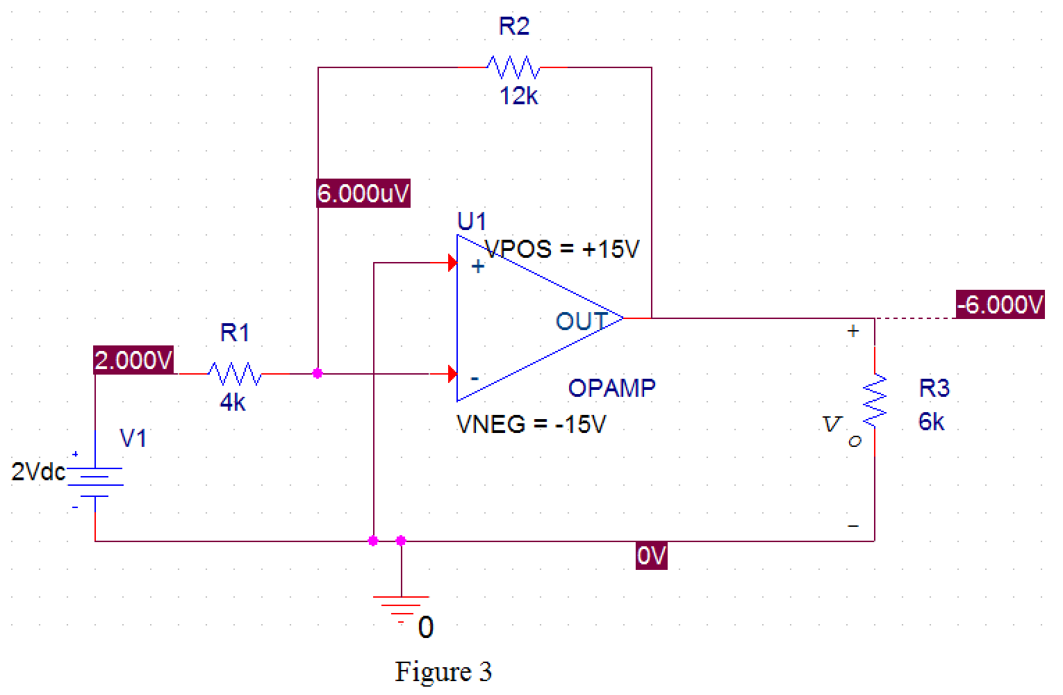
After simulating the PSPICE circuit, the output voltage

From Figure 3, the value of output voltage is
Conclusion:
Thus, the value of voltage
Want to see more full solutions like this?
Chapter 5 Solutions
EBK ELECTRIC CIRCUITS
- 2.48. Show that if y(t) = x(t)* h(t), then y' (t) = x' (1) * h(t) = x(t) * h'(t) Hint: Differentiate Eqs. (2.6) and (2.10) with respect to t. 2.49. Show that x(1) * 8'(t) = x(t) Hint: Use the result from Prob. 2.48 and Eq. (2.58).arrow_forward2.47. Compute the convolution sum y[n] = x[n]+h[n] of the following pairs of sequences: (a) x[n] = u[n], h[n] = 2"u[n] (b) x[n]=u[n]-u[n-N], h[n]=a"u[n], 0 < a <1 (c) x[n]=()"u[n], h[n] = 8[n] - 8[n-1]arrow_forward2.55. Consider a discrete-time LTI system with impulse response h[n] given by Is this system memoryless? Ans. No, the system has memory. h[n] = [n-1]arrow_forward
- "4. The load impedance connected to the secondary winding of the ideal transformer in the following circuit consists of a resistance of 237.5m2 in series with an inductor of 125µH. If the sinusoidal voltage source v, is generating the voltage 2500 cos(400t) V, calculate the steady-state equations for: (a) 21. (b) v1. (c) i₂, and (d) v2." 08 0,255 mH 237,5 m2 10:1 01 - Ideal 02 125 pharrow_forward2.55. Consider a discrete-time LTI system with impulse response h[n] given by h[n]=8[n-1] Is this system memoryless? Ans. No, the system has memory.arrow_forward"1. Formulate the matrix system to find the voltages and currents of the transformer in the following circuit. Hint: Use KVL (Kirchhoff's Voltage Law) in each winding of the transformer and use the voltage and current relationships." RT www pNp Ns Rc Vp idealarrow_forward
- 2.62. Write the input-output equation for the system shown in Fig. 2-34. Ans. 2y[n]-y[n-1] = 4x[n] + 2x[n-1] x[n] Unit delay Fig. 2-34 y[n] Σ + +arrow_forward(ii) Register B hold the data byte 28H and accumulator hold 97H. Show the contents of the registers B, C and accumulator after the execution of the following instructions. MOV A, B MOV C, Aarrow_forward2.53. The system shown in Fig. 2-31 is formed by connection two systems in parallel. The impulse responses of the systems are given by h₁(t)=eu(1) and h₂(1) = 2e'u(1) (a) Find the impulse response h(t) of the overall system. (b) Is the overall system stable? Ans. (a) h(t) = (e-21 + 2e')u(t) (b) Yes x(t) h₁(1) + h₂(1) Fig. 2-31 + y(t) Σarrow_forward
- 2.54. Consider an integrator whose input x(t) and output y(t) are related by y(t) = '_x(T) dT (a) Find the impulse response h(t) of the integrator. (b) Is the integrator stable? Ans. (a) h(t) = u(t) (b) Noarrow_forward2.61. Is the system described by the differential equation linear? Ans. No, it is nonlinear. dy(t) +5y(1)+2=x(1) dtarrow_forward2.64. Consider a discrete-time system whose input x[n] and output y[n] are related by y[n] y[n-1] = x[n] with y[-1] = 0. Find the output y[n] for the following inputs: (a) x[n]=()u[n]; (b) x[n]=()u[n] Ans. (a) y[n] = 6[()*+' - (¹)" + ¹]u[n] (b) y[n] = (n+1X)"u[n]arrow_forward
 Introductory Circuit Analysis (13th Edition)Electrical EngineeringISBN:9780133923605Author:Robert L. BoylestadPublisher:PEARSON
 Delmar's Standard Textbook Of ElectricityElectrical EngineeringISBN:9781337900348Author:Stephen L. HermanPublisher:Cengage Learning
 Programmable Logic ControllersElectrical EngineeringISBN:9780073373843Author:Frank D. PetruzellaPublisher:McGraw-Hill Education
 Fundamentals of Electric CircuitsElectrical EngineeringISBN:9780078028229Author:Charles K Alexander, Matthew SadikuPublisher:McGraw-Hill Education
 Electric Circuits. (11th Edition)Electrical EngineeringISBN:9780134746968Author:James W. Nilsson, Susan RiedelPublisher:PEARSON
 Engineering ElectromagneticsElectrical EngineeringISBN:9780078028151Author:Hayt, William H. (william Hart), Jr, BUCK, John A.Publisher:Mcgraw-hill Education,


