Understanding Motor Controls
3rd Edition
ISBN: 9781305498129
Author: Stephen L. Herman
Publisher: Cengage Learning
expand_more
expand_more
format_list_bulleted
Videos
Textbook Question
Chapter 5, Problem 15RQ
Refer to the circuit shown in Figure 5-29. In this circuit, the HR contactor is equipped with five contacts. Three are load contacts and two are auxiliary contacts. From looking at the schematic diagram, how is it possible to identify which contacts are the load contacts and which are the auxiliary contacts?
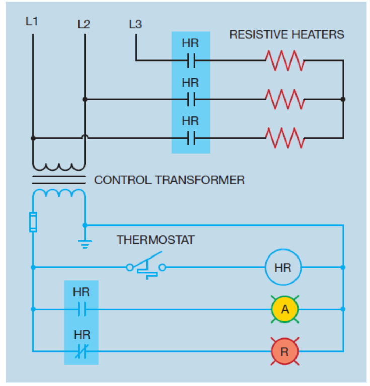
Figure 5-29 The contactor contains both load and auxiliary contacts.
Expert Solution & Answer
Want to see the full answer?
Check out a sample textbook solution
Students have asked these similar questions
Q1
---- -
Reduce the combinational logic circuit in figure 1 to minimum form.
Figure 1
B
C
D
What is the total current from the
voltage source in Figure 6-64 for each
switch position?
Figure 6-64
15 V
+
+₁₁
+₁
R₁
1.0 ΚΩ
+₁
R₂
1.8 ΚΩ
www
+₁₁
R3
2.2 ΚΩ
www
R4
2.7 ΚΩ
In relation to the circuit presented below, mark the alternative(s) that you consider correct.
1 To enable actuator A2 to advance, it is necessary to switch valve V2 to the leftmost position and ensure that valve V1 is in its initial (intermediate) position.
2 Switching valve V2 to the leftmost position allows actuator A2 to advance, but for this to happen, valve V1 must also be switched to the leftmost position.
3 When activating valve V1, using the locking lever installed on the left side of it, the two actuators (A1 and A2) are allowed to advance.
4 Hydraulic pump B1 is a simple variable displacement type.
5 Valves V1 and V2 have a TANDEM center.
Chapter 5 Solutions
Understanding Motor Controls
Ch. 5 - Prob. 1RQCh. 5 - Prob. 2RQCh. 5 - Explain the difference between auxiliary contacts...Ch. 5 - Prob. 4RQCh. 5 - What is optoisolation and what is its main...Ch. 5 - What pin numbers are connected to the coil of an...Ch. 5 - An 11-pin control relay contains three sets of...Ch. 5 - What is the purpose of the shading coil?
Ch. 5 - Refer to the circuit shown in Figure 5-29. Is the...Ch. 5 - What is the difference between a motor starter and...
Knowledge Booster


Learn more about
Need a deep-dive on the concept behind this application? Look no further. Learn more about this topic, mechanical-engineering and related others by exploring similar questions and additional content below.Similar questions
- Refer to the circuit shown in Figure 7-10. If wire number 11 were disconnected at the normally open auxiliary M contact, how would the circuit operate? Figure 7-10 Numbers are placed beside all components.arrow_forwardFollowing the procedure discussed in Chapter 7, place wire numbers on the schematic in Figure 8–7. Place corresponding wire numbers on the components shown in Figure 8–8.arrow_forwardRefer to the schematic diagram in Figure 318. Assume that the motor is not running. When the third speed push button is pressed, the motor starts in its lowest speed. After a delay of 3 seconds, the motor accelerates to second speed and 3 seconds later to third speed. After a period of about 1 minute, the fourth speed push button is pressed, but the motor does not accelerate to fourth speed. Which of the following could cause this problem? a. Control relay CR2 coil is open. b. S2 contactor coil is open. c. CR3 coil is shorted. d. S3 contactor coil is open.arrow_forward
- Refer to the circuit shown in Figure 25–5. Assume that timer TR1 is set for a delay of 10 seconds and timer TR2 is set for a delay of 5 seconds. When the START button is pressed, the motor starts. After 10 seconds the S1 contacts open and the motor continues to accelerate, but never reaches full speed. After a delay of about 30 seconds, the motor trips out on overload. Which of the following could cause this problem? TR1 coil is open. S2 coil is open. S1 coil is open. R coil is open.arrow_forwardRefer to the circuit shown in Figure 42–21. Assume that a fused jumper is connected across terminals 1 and 3 of TR2 timer. What would happen if the jumper were left in place and the FIRST SPEED push button pressed? The motor would start in its lowest speed and progress to second speed, but never increase to third speed. The motor would start operating immediately in third speed. The motor would not start. The motor would start in second speed and then increase to third speed.arrow_forwardRefer to the circuit shown in Figure 15-6. The STOP button is shown to be an emergency STOP button. What does the symbol used for the STOP button actually represent?arrow_forward
- Refer to the circuit shown in Figure 4221. Assume that the THIRD SPEED push button is pressed. The motor starts in second speed, skipping first speed. After 5 seconds, the motor accelerates to third speed. Which of the following could cause this problem? a. S1 contactor coil is open. b. CR1 contactor coil is open. c. TRl timer coil is open. d. S1 load contacts are shorted.arrow_forwardRefer to the transformer shown in Figure 5-13 to answer the following questions. What is the turns ratio of the winding between points B and E as compared to the winding between points D and E? Figure 5-13 Autotransformer practice problems.arrow_forwardRefer to the transformer shown in Figure 5-13 to answer the following questions. The transformer shown in Figure 5-13 is supplying 325 volt amperes to a load. The primary voltage is 240 volts. What is the primary current? Figure 5-13 Autotransformer practice problems.arrow_forward
- 5 position and 2-way type of ports DCV could be used in the double acting actuator circuit. Select one: True Falsearrow_forwardRefer to the circuit shown in Figure 3311. You are to construct this circuit on the job. Would it be possible to use an 11 pin control relay for 4CR?arrow_forwardWhat are the complete components used in this circuit diagram and port designationsarrow_forward
arrow_back_ios
SEE MORE QUESTIONS
arrow_forward_ios
Recommended textbooks for you
 Understanding Motor ControlsMechanical EngineeringISBN:9781337798686Author:Stephen L. HermanPublisher:Delmar Cengage Learning
 Electrical Transformers and Rotating MachinesMechanical EngineeringISBN:9781305494817Author:Stephen L. HermanPublisher:Cengage Learning
Understanding Motor Controls
Mechanical Engineering
ISBN:9781337798686
Author:Stephen L. Herman
Publisher:Delmar Cengage Learning
Electrical Transformers and Rotating Machines
Mechanical Engineering
ISBN:9781305494817
Author:Stephen L. Herman
Publisher:Cengage Learning
Mod-01 Lec-16 Basics of Instrumentation; Author: nptelhrd;https://www.youtube.com/watch?v=qbKnW42ZM5c;License: Standard YouTube License, CC-BY