
Engineering Mechanics: Statics
8th Edition
ISBN: 9781118807330
Author: James L. Meriam, L. G. Kraige, J. N. Bolton
Publisher: WILEY
expand_more
expand_more
format_list_bulleted
Concept explainers
Videos
Textbook Question
Chapter 4.4, Problem 39P
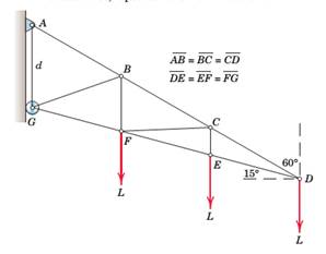
Determine the forces in members BC and CF of the loaded truss, repeated here from Prob. 4/19.
Expert Solution & Answer
Want to see the full answer?
Check out a sample textbook solution
Students have asked these similar questions
For the given truss below, the section cut a-a is taken and the free-body diagram of the outcoming leftsegment of the truss is shown below. Determine the force in the member BD and state whether it is in tension or compression. (Note: All members are weightless.)
For the truss shown below, determine the reaction and all member forces.
The compound bar is supported by a thrustbearing at A, a slider bearing at B and thecable CD. Determine the tension in the cable,the bearing reaction at A and B. Neglect theweight of the bar.
Chapter 4 Solutions
Engineering Mechanics: Statics
Ch. 4.3 - Determine the force in each member of the loaded...Ch. 4.3 - The truss of the previous problem is modified by...Ch. 4.3 - Calculate the forces in members BE and BD of the...Ch. 4.3 - Prob. 23PCh. 4.4 - Determine the force in member CG.Ch. 4.4 - Calculate the forces in members BC, BE, and EF....Ch. 4.4 - Determine the forces in members BC and CF of the...Ch. 4.6 - Determine the magnitude of the pin reactions at B...Ch. 4.6 - A 250-N force is applied to the foot-operated air...Ch. 4.6 - Determine the force acting on member ABC at...
Knowledge Booster


Learn more about
Need a deep-dive on the concept behind this application? Look no further. Learn more about this topic, mechanical-engineering and related others by exploring similar questions and additional content below.Similar questions
- For The Truss Shown, Use The Method Of Sections To Find The Internal Forces For Bars BC, BG, And FGarrow_forwardfrom the truss shown, find the force member BC and CG in kNarrow_forward4/2 Determine the force in each member of the loaded truss. Discuss the effects of varying the angle of the 45 support surface at C.arrow_forward
- The figure shows a three-pin arch. Determine the horizontal component of the pin reaction at A caused by the applied force P.arrow_forwardThe hinge shown is the type used on the doors of some automobiles. If a torsion spring at F applies the constant couple C0=20lbft to member ABF, calculate the force P required to hold the door open in the position shown.arrow_forwardFind the magnitude and nature of the forces in all the members of the given truss. Figure: 3aand 3barrow_forward
- Q. 4: The 420 lb homogeneous log weight 420 lb, is supported by a rope at A and losse-fitting rollers at B and C as it is being fed into a sawmill. Calculate the tension in the rope and the reactions at the rollers. 30arrow_forwardFor the frame shown, determine the magnitude if the pin reaction at B. Neglect the weight of the frame.arrow_forwardFor the truss loaded below, find the force in member KJ, KD, and CD using method of sections. State whether the members are in tension or compression. 4. K Summary: 3 m Force (kN) Member KJ B C E F KD CD -2 m--2 m--2 m--2 m--2 m-2 m- 20 kN 30 kN 40 kNarrow_forward
- Please help me identify the zero force members in this truss.arrow_forwardDraw the free body diagrams of (a) the whole structure, (b) members AB, BC and AC individually and (c) the pin at B. The forces in the free body diagrams must be named consistently.arrow_forwardStop Share The horizontal boom AO is supported by cables AB and CD, and a ball-and-socket joint at O. Calculate the tensions in the cables, and support reactions at O in terms of x. Neglect weight of the boom. L=10 kN, a= 7 m, b=3 m, c-2 m, d=4 m x A C B X b C Darrow_forward
arrow_back_ios
SEE MORE QUESTIONS
arrow_forward_ios
Recommended textbooks for you
 International Edition---engineering Mechanics: St...Mechanical EngineeringISBN:9781305501607Author:Andrew Pytel And Jaan KiusalaasPublisher:CENGAGE L
International Edition---engineering Mechanics: St...
Mechanical Engineering
ISBN:9781305501607
Author:Andrew Pytel And Jaan Kiusalaas
Publisher:CENGAGE L
Engineering Basics - Statics & Forces in Equilibrium; Author: Solid Solutions - Professional Design Solutions;https://www.youtube.com/watch?v=dQBvQ2hJZFg;License: Standard YouTube License, CC-BY