
Electric Circuits (10th Edition)
10th Edition
ISBN: 9780133760033
Author: James W. Nilsson, Susan Riedel
Publisher: PEARSON
expand_more
expand_more
format_list_bulleted
Concept explainers
Videos
Textbook Question
Chapter 4.2, Problem 1AP
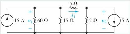
a) For the circuit shown, use the node-voltage method to find v1, v2, and i1.
b) How much power is delivered to the circuit by the 15 A source?
c) Repeat (b) for the 5 A source.
Expert Solution & Answer

Learn your wayIncludes step-by-step video

schedule06:29
Students have asked these similar questions
Using the circuit, determine thevenin’s voltage(Vth) and thevenin's resistance(Rth) for load resistor R1. Then solve for I1. Draw all diagrams.
Discussion:-
Does K.C.L. & K.V.L depend on the relationship between current
and voltage in a resistor, Explain?
2- Explain why two voltage sources of different voltage rating cannot
be connected in parallel. What is the corresponding statement for
current sources?-
Show that for a circuit with (n) nodes it is sufficient to write the
K.C.L. for (n-1) nodes and that the K.C.L. for Nth node is not
independent (support your answer with an auou
Topic: Direct Current Circuit which contains Open and Short Circuit, Series and Parallel Circuit, Current Divider Principle, Voltage Divider Prinicple, and Delta-Wyne Connection.
Determine the value of VT and I.
Note: DRAW THE DIAGRAM
Chapter 4 Solutions
Electric Circuits (10th Edition)
Ch. 4.2 - a) For the circuit shown, use the node-voltage...Ch. 4.2 - Use the node-voltage method to find v in the...Ch. 4.3 - Use the node-voltage method to find the power...Ch. 4.4 - Use the node-voltage method to find vo in the...Ch. 4.4 - Use the node-voltage method to find v in the...Ch. 4.4 - Use the node-voltage method to find v1 in the...Ch. 4.5 - Use the mesh-current method to find (a) the power...Ch. 4.6 - Determine the number of mesh-current equations...Ch. 4.6 - Use the mesh-current method to find vo in the...Ch. 4.7 - Use the mesh-current method to find the power...
Ch. 4.7 - Use the mesh-current method to find the mesh...Ch. 4.7 - Use the mesh-current method to find the power...Ch. 4.8 - Find the power delivered by the 2 A current source...Ch. 4.8 - Find the power delivered by the 4 A current source...Ch. 4.9 - Use a series of source transformations to find the...Ch. 4.10 - Find the Thévenin equivalent circuit with respect...Ch. 4.10 - Prob. 17APCh. 4.10 - Prob. 18APCh. 4.11 - Find the Thévenin equivalent circuit with respect...Ch. 4.11 - Find the Thévenin equivalent circuit with respect...Ch. 4.12 - Find the value of R that enables the circuit shown...Ch. 4.12 - Assume that the circuit in Assessment Problem 4.21...Ch. 4 - For the circuit shown in Fig. P4.1, state the...Ch. 4 - If only the essential nodes and branches are...Ch. 4 - Assume the voltage vs in the circuit in Fig. P4.3...Ch. 4 - A current leaving a node is defined as...Ch. 4 - How many separate parts does the circuit in Fig....Ch. 4 - Use the node-voltage method to find vo in the...Ch. 4 - Find the power developed by the 40 mA current...Ch. 4 - A 50 Ω resistor is connected in series with the 40...Ch. 4 - Use the node-voltage method to find how much power...Ch. 4 - Use the node-voltage method to show that the...Ch. 4 - Use the node-voltage method to find the branch...Ch. 4 - Use the node-voltage method to find v1 and v2 in...Ch. 4 - Use the node-voltage method to find v1 and v2 in...Ch. 4 - Use the node-voltage method to find v1, v2, and v3...Ch. 4 - The circuit shown in Fig. P4.14 is a dc model of a...Ch. 4 - Use the node-voltage method to find the total...Ch. 4 - Use the node-voltage method to find vo in the...Ch. 4 - Use the node-voltage method to calculate the power...Ch. 4 - Use the node-voltage method to find the total...Ch. 4 - Use the node voltage method to find vo for the...Ch. 4 - Find the node voltages v1, v2, and v3 in the...Ch. 4 - Use the node-voltage method to find υ0 and the...Ch. 4 - Use the node-voltage method to find the value of...Ch. 4 - Use the node-voltage method to find io in the...Ch. 4 - Use the node-voltage method to find the power...Ch. 4 - Use the node-voltage method to find vo in the...Ch. 4 - Use the node-voltage method to find the branch...Ch. 4 - Use the node-voltage method to find the value of...Ch. 4 - Assume you are a project engineer and one of your...Ch. 4 - Use the node-voltage method to find the power...Ch. 4 - Show that when Eqs. 4.13, 4.14, and 4.16 are...Ch. 4 - Use the mesh-current method to find the branch...Ch. 4 - Solve Problem 4.11 using the mesh-current...Ch. 4 - Solve Problem 4.14 using the mesh-current...Ch. 4 - Solve Problem 4.26 using the mesh-current...Ch. 4 - Use the mesh-current method to find the total...Ch. 4 - Solve Problem 4.25 using the mesh-current...Ch. 4 - Solve Problem 4.17 using the mesh-current...Ch. 4 - Use the mesh-current method to find the power...Ch. 4 - Use the mesh-current method to find the power...Ch. 4 - Use the mesh-current method to find υ0 in the...Ch. 4 - Use mesh-current method to find the power...Ch. 4 -
Use the mesh-current method to solve for iΔ in...Ch. 4 - Solve Problem 4.10 using the mesh-current...Ch. 4 - Solve Problem 4.21 using the mesh-current...Ch. 4 - Use the mesh-current method to find the total...Ch. 4 - Use the mesh-current method to find how much power...Ch. 4 - Use the mesh-current method to determine which...Ch. 4 - Use the mesh-current method to find the total...Ch. 4 - Prob. 50PCh. 4 - Solve Problem 4.23 using the mesh-current...Ch. 4 - Use the mesh-current method to find the branch...Ch. 4 - Find the branch currents ia − ie for the circuit...Ch. 4 - Assume you have been asked to find the power...Ch. 4 - A 4 kΩ resistor is placed in parallel with the 10...Ch. 4 - Would you use the node-voltage or mesh- current...Ch. 4 - Prob. 57PCh. 4 - The variable de voltage source in the circuit in...Ch. 4 - Make a series of source transformations to find...Ch. 4 - Prob. 60PCh. 4 - Use source transformations to find the current io...Ch. 4 - Use a series of source transformations to find i0...Ch. 4 - Use source transformations to find vo in the...Ch. 4 - Prob. 64PCh. 4 - Find the Norton equivalent with respect to the...Ch. 4 - Prob. 66PCh. 4 - Find the Thévenin equivalent with respect to the...Ch. 4 - Prob. 68PCh. 4 - A Thévenin equivalent can also be determined from...Ch. 4 - Prob. 70PCh. 4 - Prob. 71PCh. 4 - Prob. 72PCh. 4 - The Wheatstone bridge in the circuit shown in Fig....Ch. 4 - Prob. 74PCh. 4 - Find the Norton equivalent with respect to the...Ch. 4 - Prob. 76PCh. 4 - Prob. 77PCh. 4 - Find the Thévenin equivalent with respect to the...Ch. 4 - Find the Thévenin equivalent with respect to the...Ch. 4 - Prob. 80PCh. 4 - Find the Norton equivalent with respect to the...Ch. 4 - The variable resistor in the circuit in Fig. P4.82...Ch. 4 - Prob. 83PCh. 4 - a) Calculate the power delivered for each value of...Ch. 4 - Find the value of the variable resistor Ro in the...Ch. 4 - A variable resistor R0 is connected across the...Ch. 4 - The variable resistor (R0) in the circuit in Fig....Ch. 4 - The variable resistor in the circuit in Fig. P4.91...Ch. 4 - The variable resistor (RL) in the circuit in Fig....Ch. 4 - The variable resistor (RO) in the circuit in Fig....Ch. 4 - In the circuit in Fig. P4.92, before the 5 mA...Ch. 4 - Use the principle of superposition to find the...Ch. 4 -
Use superposition to solve for and υ0 in the...Ch. 4 - Prob. 95PCh. 4 - Use the principle of superposition to find the...Ch. 4 - Prob. 97PCh. 4 - Use the principle of superposition to find the...Ch. 4 - Assume your supervisor has asked you to determine...Ch. 4 - Prob. 100PCh. 4 - Prob. 101PCh. 4 - Prob. 102PCh. 4 - Laboratory measurements or a dc voltage source...Ch. 4 - Prob. 104PCh. 4 - Prob. 105PCh. 4 - Repeat Problem 4.105 if Ig2 increases to 17 A and...Ch. 4 - Prob. 107PCh. 4 - Use the results given in Table 4.2 to predict the...
Additional Engineering Textbook Solutions
Find more solutions based on key concepts
For the network of Fig. 8.104: a. Determine the currents I1 and I2. b. Calculate the voltages V2 and Vs. Fig. 8...
Introductory Circuit Analysis (13th Edition)
Broadly speaking, what are the two main objectives of electrical systems?
Electrical Engineering: Principles & Applications (7th Edition)
The switch in the bottom loop of Fig. P6.1 is closed at t = 0 and then opened at a later time t1. What is the d...
Fundamentals of Applied Electromagnetics (7th Edition)
Explain why a classs copy constructor is called when an object of that class is passed by value into a function...
Starting Out with C++: Early Objects
In Exercises 27 through 34, identify any errors. DimmAsDecimal,nAsIntegerm=3.45n=2.0+3.0
Introduction to Programming Using Visual Basic (10th Edition)
Write a program that demonstrates the approximate nature of floating-point values by performing the following t...
Java: An Introduction to Problem Solving and Programming (7th Edition)
Knowledge Booster


Learn more about
Need a deep-dive on the concept behind this application? Look no further. Learn more about this topic, electrical-engineering and related others by exploring similar questions and additional content below.Similar questions
- 7. For the network in figure a. the short-circuit currents I, and I. b. the voltages V, and V2. c. the source current I,. determine 10 N + 20 V V2 50arrow_forward(a) State the Kirchhoffs law of voltage and current. with the support of a simple circuit diagram, show how the Kirchhoffs law can be used to divide source voltage among circuit elements. Use the case of only two elements.arrow_forwardFor the circuit shown in figure below, Calculate V1, V2, I1, I2, I3, I4 and power dissipationthrough R4. ?arrow_forward
- 1. Identify all the nodes in the circuit. Label them (N,, N2 ..). 2. Identify and draw the current direction. Label (I,, 12 .) 3. Write the equation for each of the node. 4. Draw the loops. Label (L1, L2 ...) 5. Write the equation for each of the loop. V2 Rz Rg the Rsarrow_forwardSolve the following: (a) Current I (b) Vd (c) Power of Vs and Vd (d) state whether Vs and Vd is delivering or absorbing power.arrow_forward1. Using Series-Parallel concept, Find the following for the given circuit. The value of the power supply and resistances are given in Page-4. a) the current supplied by the source b) the voltage drops across each resistor c) the r dissipated by R3 R1=45kn R2=2kn R3=22kQ R4=14kn R5=17kn R6=85kn V1=24 v R₁ R₂ V₁ R₂ R₂ R₂arrow_forward
- In the Node Voltage Method, a system of equations is written to solve for which of the following? O Component voltages. O Node voltages. O Branch currents. O Currents through voltage sources.arrow_forwardWhat if it would have been asked only a current source and a resistor simply seen from the output terminals, give the name of this configuration. Using the simple circuit , convert it into 1 current source & 1 resistor format by applying source transformation.arrow_forwardB2 Determine the value of the load resistance Rı. shown in figure that give s maximum power dissipation. Also find the value of the power. 24V I RL 82arrow_forward
- Problem 3: Question Consider the circuit diagram below. The circuit supplies power to the unknown resistive load, L. Determine the Thevenin equivalent circuit for the supply circuit. Verify that your Thevenin equivalent is indeed equivalent to the original circuit by simulating both circuits using CircuitJS and reporting the load current in each. Attach an exported image or screen shot of both of your circuits from CircuitJS with the current and voltage "shown" (colors are shown on the diagram). E₁ 10 V 4₁ 10 mA R₁ 1 ΚΩ www H₁₁ 5,50 www R₂ 25 ΚΩ R3 15 ΚΩ www R4 5 ΚΩ ww Larrow_forwardDifferentiate between Kirchhoff's Voltage Law and Kirchhoff's Current Law. Support you answer by appropriate example. Debate that how these laws are supportive to solve complex circuits.arrow_forwardSolve the direct current circuit given below by writing the node voltages and ambient currents methods and the circuit equations separately. Calculate the node voltages V1, V2 and V3 and the currents and powers of the resistors for both methods. Give all the results in a tablearrow_forward
arrow_back_ios
SEE MORE QUESTIONS
arrow_forward_ios
Recommended textbooks for you
 Introductory Circuit Analysis (13th Edition)Electrical EngineeringISBN:9780133923605Author:Robert L. BoylestadPublisher:PEARSON
 Delmar's Standard Textbook Of ElectricityElectrical EngineeringISBN:9781337900348Author:Stephen L. HermanPublisher:Cengage Learning
 Programmable Logic ControllersElectrical EngineeringISBN:9780073373843Author:Frank D. PetruzellaPublisher:McGraw-Hill Education
 Fundamentals of Electric CircuitsElectrical EngineeringISBN:9780078028229Author:Charles K Alexander, Matthew SadikuPublisher:McGraw-Hill Education
 Electric Circuits. (11th Edition)Electrical EngineeringISBN:9780134746968Author:James W. Nilsson, Susan RiedelPublisher:PEARSON
 Engineering ElectromagneticsElectrical EngineeringISBN:9780078028151Author:Hayt, William H. (william Hart), Jr, BUCK, John A.Publisher:Mcgraw-hill Education,
Introductory Circuit Analysis (13th Edition)
Electrical Engineering
ISBN:9780133923605
Author:Robert L. Boylestad
Publisher:PEARSON
Delmar's Standard Textbook Of Electricity
Electrical Engineering
ISBN:9781337900348
Author:Stephen L. Herman
Publisher:Cengage Learning
Programmable Logic Controllers
Electrical Engineering
ISBN:9780073373843
Author:Frank D. Petruzella
Publisher:McGraw-Hill Education
Fundamentals of Electric Circuits
Electrical Engineering
ISBN:9780078028229
Author:Charles K Alexander, Matthew Sadiku
Publisher:McGraw-Hill Education
Electric Circuits. (11th Edition)
Electrical Engineering
ISBN:9780134746968
Author:James W. Nilsson, Susan Riedel
Publisher:PEARSON
Engineering Electromagnetics
Electrical Engineering
ISBN:9780078028151
Author:Hayt, William H. (william Hart), Jr, BUCK, John A.
Publisher:Mcgraw-hill Education,
Nodal Analysis for Circuits Explained; Author: Engineer4Free;https://www.youtube.com/watch?v=f-sbANgw4fo;License: Standard Youtube License