
Concept explainers
Videos
The circuit and transistor parameters for the source−follower amplifier shown in Figure 4.29 are
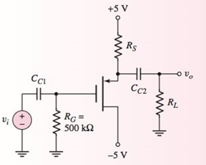
Figure 4.29 Figure for Exercise Ex 4.8
(a)
The value of width to length ratio of MOSFET.
Answer to Problem 4.8EP
Explanation of Solution
Given Information:
The given circuit is shown below.

Calculation:
The coupling capacitor acts like open circuit for DC value calculation.
The modified figure is:
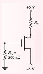
From the circuit:
Hence, transistor operates in saturation region.
The expression of drain current is:
(b)
The value of small signal voltage gain.
Answer to Problem 4.8EP
Explanation of Solution
Given Information:
The given circuit is shown below.

Calculation:
The value of
The coupling capacitor acts like short circuit for AC value calculation. The DC voltage source is short circuited.
The modified figure is:
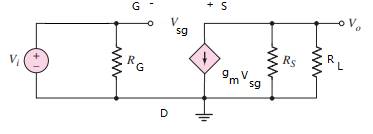
The value of output voltage is:
Applying Kirchhoff’s voltage law from input to output:
From equation (1):
Plugging the values:
(c)
The value of load resistance
Answer to Problem 4.8EP
Explanation of Solution
Given Information:
The given circuit is shown below.
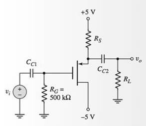
Calculation:
The new value of voltage gain is:
The value of load resistance is determined as follows:
Want to see more full solutions like this?
Chapter 4 Solutions
MICROELECT. CIRCUIT ANALYSIS&DESIGN (LL)


- Q4: Design a buck converter such that the output voltage varies between from 20V to 28V while the input voltage is 40V. The maximum load power is 200Wdc. Assume the switching frequency is 15kHz. (a) Design the converter such that it will be in continuous current mode. (b) The capacitor realized output voltage ripple must not be more than 1% at worst case. (c) The inductance realizes CCM at worst case. (d) Select the appropriate switch and other elements...arrow_forwardB: Find the value of RB for the Si transistor circuit as shown in the figure, where the operating point is exactly at the center of the load line, Vcc = 14V, Rc RE = 2KN and B=75. Vcc Rc RB REarrow_forward4. A certain common-emitter amplifier has a voltage gain of 100. If the emitter bypass capacitor is removed, (a) The circuit will become un stable (c) The voltage gain will increase (b) the voltage gain will decrease (d) the Q-point will shift 5. For a common-collector amplifier, RE =1002, r'e= 10 2, and Bac=150. The ac input resistance at the base is: (a) 1500 2 (b) 15 k2 (c) 110 Q (d) 16.5 k2 6. If a 10 mV signal is applied to the base of the emitter-follower circuit in Question 5, the output signal is approximately (a) 100 mV (b) 150 mV (c) 1.5 V (d) 10 mVarrow_forward
- Given IDSS = 8mA and Vp= -4V. Sketch the drain and transconductance curve for VGS = +2V,+1V.arrow_forward6.4) Explain conceptually whygm( sat) andgare the same. Where, g is conductance and gm(sat) is saturation transconductance.arrow_forwardFor the circuit of Figure 2. Carry out the analysis in DC and small signal with www.w www www.www Vt=0.7 V, Kn(W/L) = 4 mA/V. Ignore the Early effect. Determine: (a) The current in DC ID. (b) The gains vo/v₁, io/ii (c) The input resistance Rin and output resistance Rout. wwwwww 06402 www Ca HH {ama Ο ΜΩ www.11 Figura 2: 0.51 k www.li 12 V • 27 ΚΩ Ca +1₁ -0% 4.7 karrow_forward
- Q4: Design a buck-boost converter to provide an output voltage 12V from a source that varies 'between 10V-16V. Given the load resistor is 10 2, assuming the frequency is 50 KHz and the output voltage ripple is 1.5% Specify: a. The duty ratio. b. The value of inductor. c. The value of capacitor. Note: Determine the values of inductor and capacitor with DI only.arrow_forwardQ4. Design a DSB-SC modulator to generate a signal, k m(t) cos(2ax(300)x(10')t). The following equipments are available in the stock room: i) a signal generator of frequency 100 kHz; ii) a ring modulator and transformers; iii) a BPF tuned to 300 kHz; iv) a LPF with feutoif fm nte the desired signal and find the value of constant k?arrow_forwardLAB 5.pdf File C:/Users/Asus/Desktop/SEMESTER%20SUBJECTS/SEM%20... Not sy of 7 A PRE-LAB CALCULATION Determine the small-signal voltage gain, Av of the cireuit in Figure 1. Given forward transfer conductance, gm=2000uS. 20 V 200k 2.2k 2.2uF A 2.2uF RL HE 1k RS 50k 1k FIGURE 1 PROCEDURE Part A: AC Analysis i. Construct the amplifier circuit as shown in Figure 1. ii. Set the signal generator output to 0.5 Vp-p at 5 kHz. . Measure Vinp-p and Voutp-p Determine the gain Av. Part B: Output Impedance O lype here to searcharrow_forward
- Using the re model circuit, determine the total voltage gain for the BJT circuit shown below. Show the details of your work. 22V ... 5.6k0 330k Vo + 10UF-POL B = 80 1200 10UF-POL To = 40 kN 2N2221 6.8k) Vs 4700 22UF-POLarrow_forwardQuestion 4 Consider a BJT amplifier cireuit in Figure 4. Assume that BDC = 110, Bac- 100 remains constant during the operating conditions and Ri =2 k2. Vec +30V Rc 3 kn C, Vout R 20k 10uF Vin o 10 uF R 2kn R: Skn RE 1 ka 10 uF Figure 4 (a) Draw the de and ac equivalent cireuit for the BJT amplifier circuit. (b) Calculate the following values for the amplifier: Va, Vr, Ir, r'e, Riche Ruun, and A. (e) Evaluate the effect to the voltage gain if the bypass capacitor C2 and load resistor R, is removed from the amplifier. (d) Modify the circuit in Figure 4 to minimize the effect of r'e without reducing the voltage gain to its minimum value.arrow_forwardConsider the circuit in Figure A4. (a) Explain its operation with the aid of diagrams. (b) Assume that R₁ = 21 kQ, Vref = 1.2 V, Vs = +12 V and -Vs = -12 V. Determine a value for R₂ to obtain a maximum threshold voltage of Vth = 5.25 V. (c) Sketch the output voltage signal in time for a sinusoidal input signal of peak voltage 3.5 V and frequency 2 kHz. R1 R2 Vout Vref Vin +Vs -Vs Figure A4arrow_forward
 Introductory Circuit Analysis (13th Edition)Electrical EngineeringISBN:9780133923605Author:Robert L. BoylestadPublisher:PEARSON
 Delmar's Standard Textbook Of ElectricityElectrical EngineeringISBN:9781337900348Author:Stephen L. HermanPublisher:Cengage Learning
 Programmable Logic ControllersElectrical EngineeringISBN:9780073373843Author:Frank D. PetruzellaPublisher:McGraw-Hill Education
 Fundamentals of Electric CircuitsElectrical EngineeringISBN:9780078028229Author:Charles K Alexander, Matthew SadikuPublisher:McGraw-Hill Education
 Electric Circuits. (11th Edition)Electrical EngineeringISBN:9780134746968Author:James W. Nilsson, Susan RiedelPublisher:PEARSON
 Engineering ElectromagneticsElectrical EngineeringISBN:9780078028151Author:Hayt, William H. (william Hart), Jr, BUCK, John A.Publisher:Mcgraw-hill Education,